Optics Subassemblies
The optics consists of the following subassembly
Projector Mount
Collimating Lens Mounts
Collimating Lens Mounts
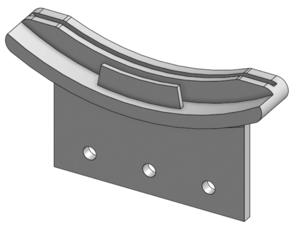
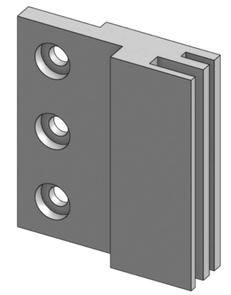
Required Materials:
(QTY 1) Col Lens Bottom Mount
(QTY 2) Col Lens Side Mount
(QTY 9) M5x8 Button Head Screw
(QTY 9) M5 Hammer TNut
Required Tools:
No Tools Required.
Step-by-Step Instructions
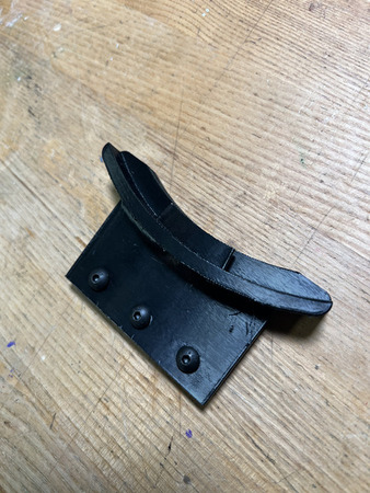
Place QTY (3) M5x8 Button Head Screw through each of the holes on the QTY (1) Col Lens Bottom Mount from the front (see image below). Loosely install QTY (3) M5 Hammer TNut on the opposite ends.
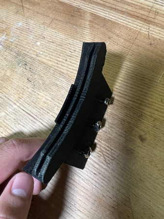
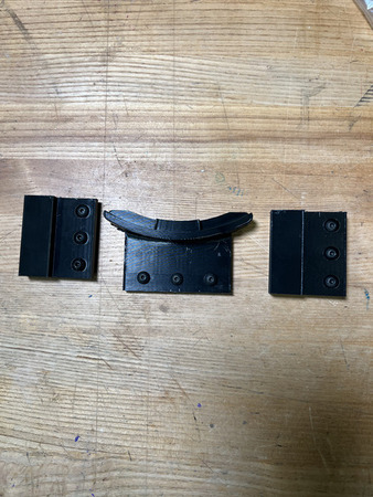
Place QTY (6) M5x8 Button Head Screw through each of the holes on the QTY (2) Col Lens Side Mount from the front (counterbores). Loosely install QTY (6) M5 Hammer TNut on the opposite ends.
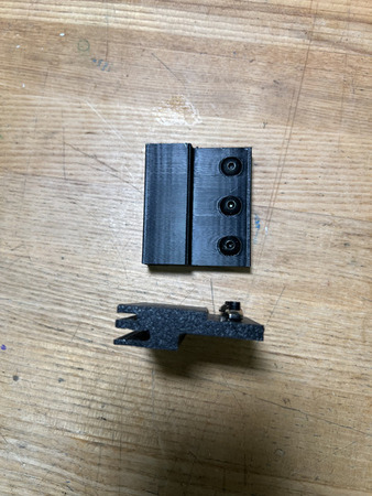
The Collimating Lens Mounts subassembly is now complete.
Projector Mount Support
Required Materials:
NOTE: Heat Set Inserts have already been installed into Projector Support Base.
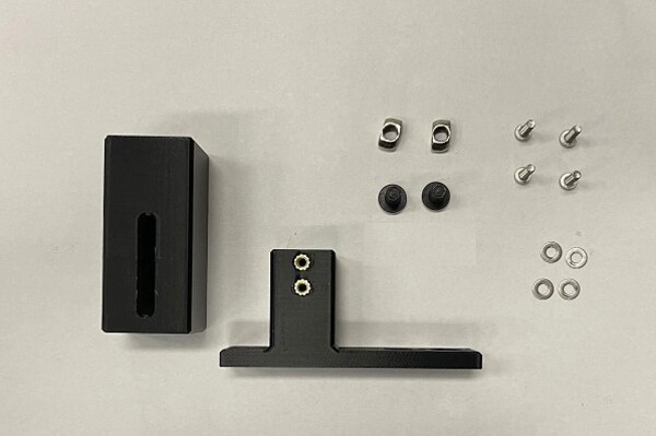
(QTY 1) Projector Support Mount
(QTY 1) Projector Support base
(QTY 4) M3x4x5 Heat Set Insert
(QTY 4) M3x12 Button Head Screw
(QTY 4) M3 Washer
(QTY 2) M5x8 Button Head Screw
(QTY 2) M5 Hammer Tnut
Required Tools:
M2 Allen/Hex Key
Soldering Iron
Step-by-Step Instructions
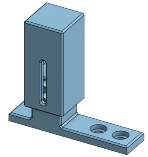
Slide QTY (1) Projector Top Support over the extrusion on QTY (1) Projector Support Base. Through the slot on the Projector Support Mount, install QTY (2) M3x12 Button Head Screw & QTY (2) M3 Washer on BOTH sides. The mount can be slid at an arbitrary point for now.
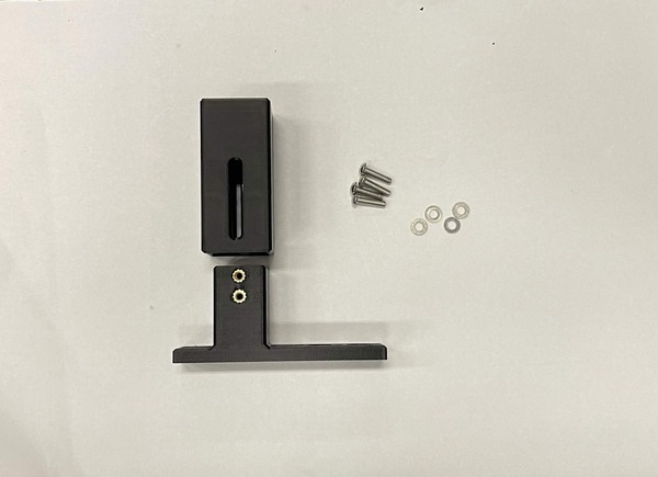
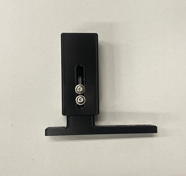
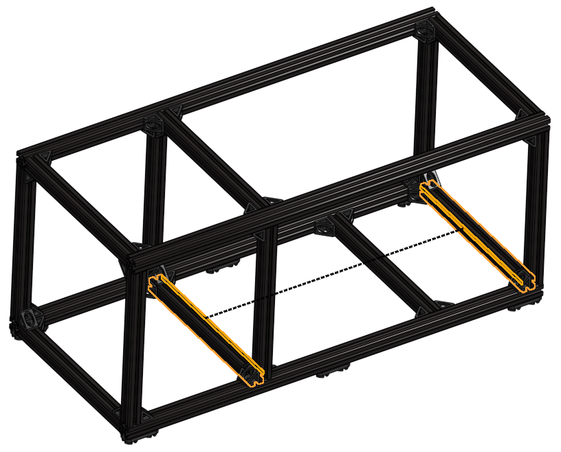
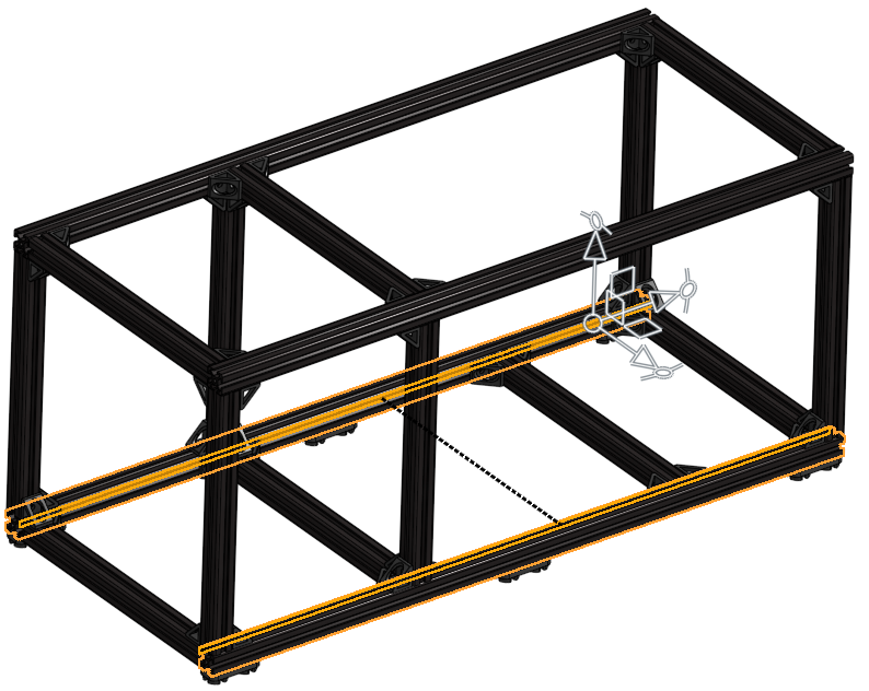
Loosely install QTY (2) M5x8 Button Head Screw with QTY (2) M5 Hammer TNut in the location below.
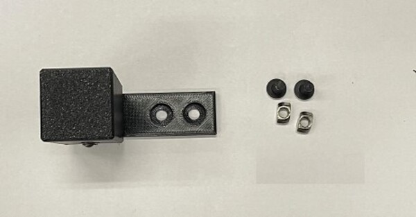
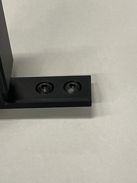
The Projector Support Subassembly is now complete.
Projector Mount
NOTE: These instructions are for the NexiGo Nova Mini Laser Projector.
Tip
Before mounting the projector, disable its auto focus and WiFi in the projector’s own settings menu. This is much easier to do now, while the projector is still loose, than once it is installed in the machine.
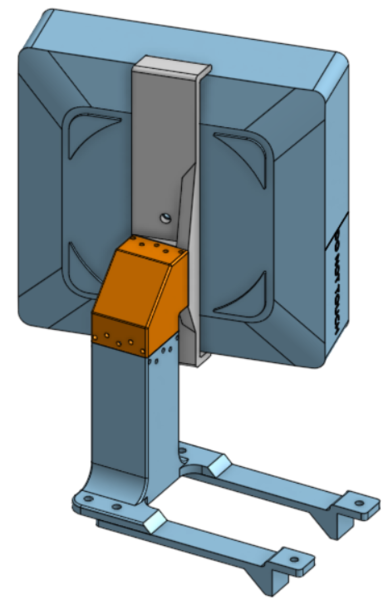
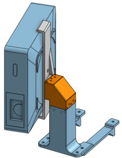
Required Materials:
(QTY 1) Projector (NexiGo Nova Mini)
(QTY 1) Projector Interface
(QTY 1) XZ Stage
(QTY 1) Projector Stand
(QTY 1) XY Core
(QTY 2) Y Locator
(QTY 12) M3x40mm Stainless Steel Rod
(QTY 3) M3x40 Socket Head Screw
(QTY 3) 6x0.8x25mm Compression Spring
(QTY 9) M3 Hex Nuts
(QTY 3) M3 Washer
(QTY 1) 1/4-20x1/2 Button Head Screw
(QTY 4) M5x10 Button Head Screw
(QTY 4) M5 Hammer TNut
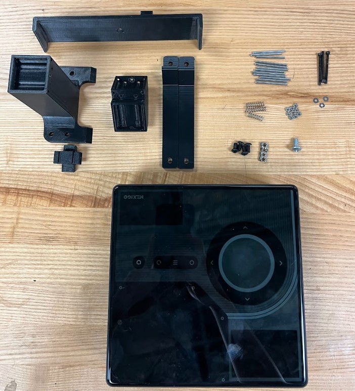
Required Tools:
Wire Cutter
M2.5 Hex/Allen Key
Needle Nose Pliers (recommended)
Step-by-Step Instructions
NOTE: Unless otherwise mentioned, all fasteners will be “hand tight”. The “front” of the projector stand is the flat side. To press in the Steel Rods, it is recommended to use Needle Nose Pliers. Always ensure the rods are flush with the 3D print.
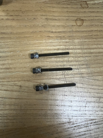
Screw on QTY (2) M3 Hex Nut on QTY (1) M3x40 Socket Head Screw and then place QTY (1) M3 Washer over.
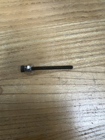
Repeat this 2 more times. You should have 3 of these assemblies total.
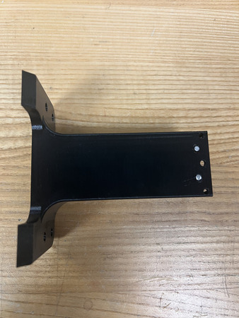
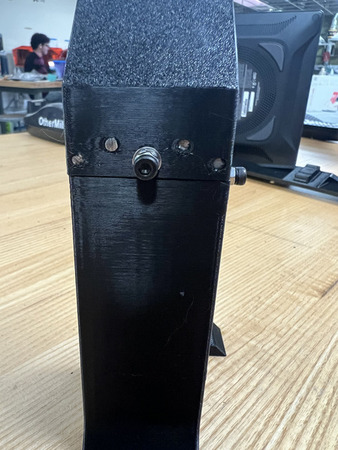
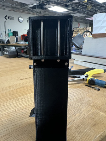
Lay the QTY (1) Projector Stand on the flat side. Press in QTY (2) M3x40mm Stainless Steel Rod into the bottom center locations (see image below).
The QTY (1) XY Core has two hex holes and two circular holes for M3 Hex Nuts and M3 Screws respectively. On the top hole, screw the assembly from Step 2 through the circular hole until it comes out the hex hole. Screw on QTY (1) M3 Hex Nut. Grab the head of the M3 Socket Screw and pull it so that the hex nut goes in the hex hole and is as deep in the hex hole as possible. Remove the screw from the M3 Hex Nut, ensuring that the M3 Hex Nut remains deep in the hex hole.
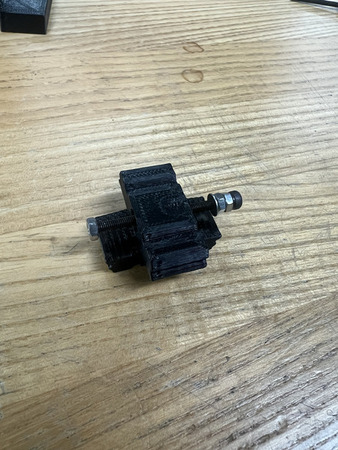
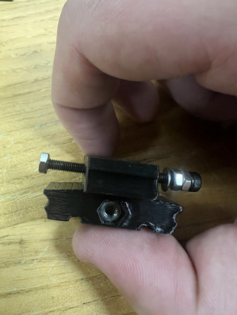
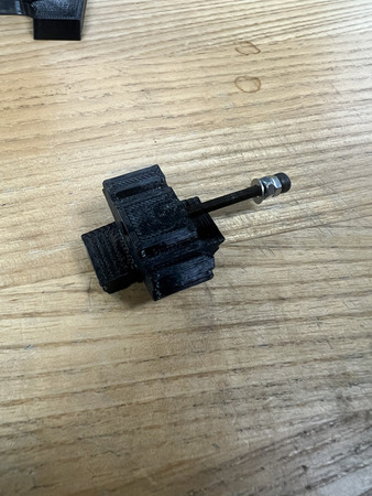
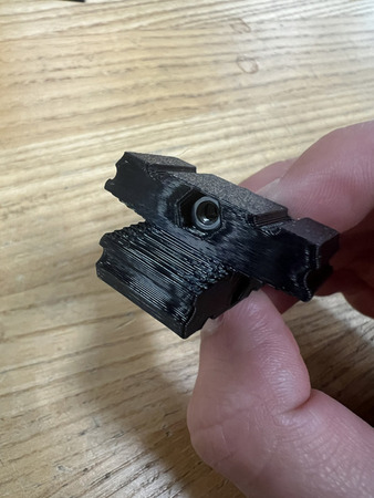
Repeat Step 4 with the bottom hole on the QTY (1) XY Core.
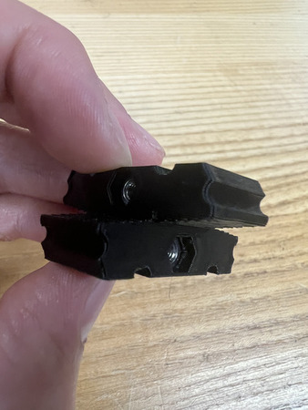
Press in QTY (2) 6x0.8x25 mm Compression Spring into each of the circular holes on the QTY (1) XY Core.
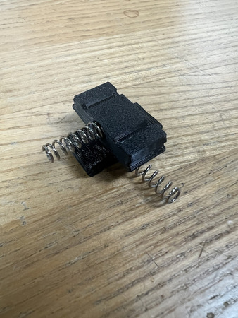
Place the assembly from Step 6 within the top hole on the assembly from Step 3. Orient it so that the bottom spring interfaces with the top center hole on the back of the Projector Stand.
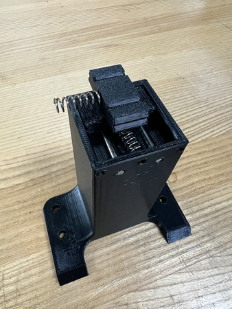
Screw in one of the assemblies from Step 2 through the center hole that is interfacing with the spring mentioned in the previous step. Keep turning until you feel it engage all the way through the nut. For the upcoming steps, it is good to center the XY Core. Do this by tightening the M3x40 Screw assembly.
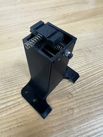
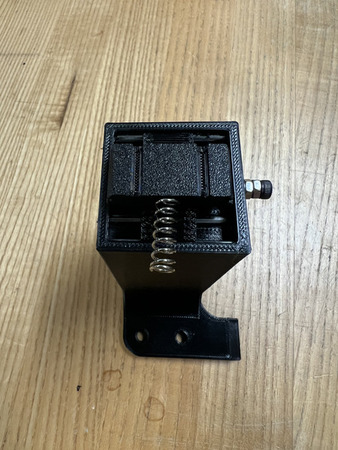
Press in QTY (2) M3x40 Stainless Steel Rods through the other through holes at the back of the Projector Stand. Ensure that these rods also go through the slots on the XY Core. This core should be stabilized after the rods are inserted.
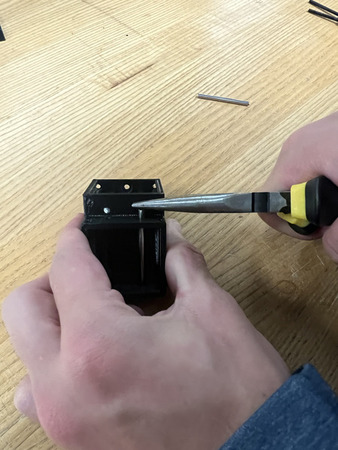
Press in QTY (4) M3x40 Stainless Steel Rod into the center two holes on each side of the QTY (1) XZ Stage (see image below).
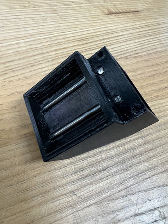
Take the assembly from the previous step and place it over the Projector Stand. Move it so that it is over the spring where the spring is interfacing with the bottom center hole on the XZ Stage. The XZ Stage is symmetrical.
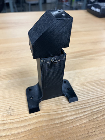
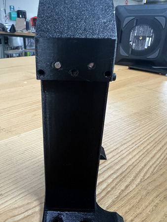
Screw in another one of the assemblies from Step 2 through this bottom center hole such that it is interfacing with the spring mentioned in the previous step. Keep turning until you feel it engage all the way through the nut.
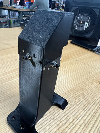
Press in QTY (2) M3x40 Stainless Steel Rods through the other through holes of the QTY (1) XZ Stage. Ensure that these rods also go through the slots on the XY Core.
Press on the QTY (1) Projector Interface onto the QTY (1) Projector such that the flat sides are parallel with the face of the lens. Ensure the larger flat is faces the opposite side of the lens and that the rotation stage is aligned with the lens (see image below). Screw down using QTY (1) 1/4-20x1/2 Button Head Screw.
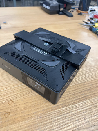
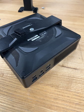
The QTY (1) Projector Interface has a hex hole and a circular hole for a M3 Hex Nut and M3 Screw respectively. Screw the assembly from Step 2 through the circular hole until it comes out the hex hole. Screw on QTY (1) M3 Hex Nut slightly. Grab the head of the M3 Socket Screw and pull it so that the hex nut goes in the hex hole and is as deep in the hex hole as possible. Remove the screw from the M3 Hex Nut, ensuring that the M3 Hex Nut remains deep in the hex hole.
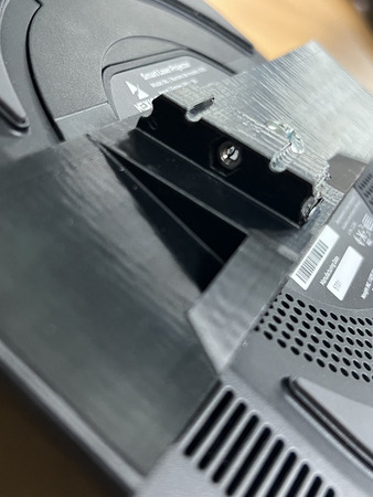
Press in QTY (1) 6x0.8x25 mm Compression Spring into the circular holes on the QTY (1) Projector Interface.
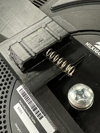
Take the assembly from Step 13 and place it over the QTY (1) Projector Interface so that it grabs the spring from the previous step. The spring should interface with the top center hole of the Step 13 assembly. Ensure it is oriented such that the base of the Step 13 assembly is closer to the lens.
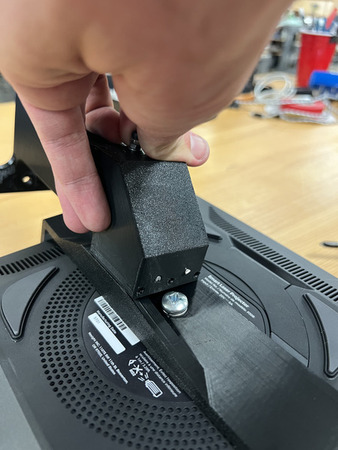
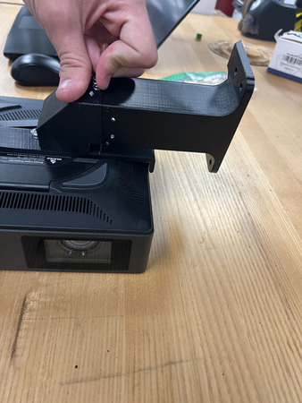
Screw in the last assembly from Step 2 through the center hole such that it goes through the spring and M3 nut. Keep turning until you feel it engage all the way through the nut.
Insert QTY (2) M3x40 Stainless Steel Rods through the two side holes of the Step 13 assembly (from the top). Ensure the rods go through the slots on the Projector Interface
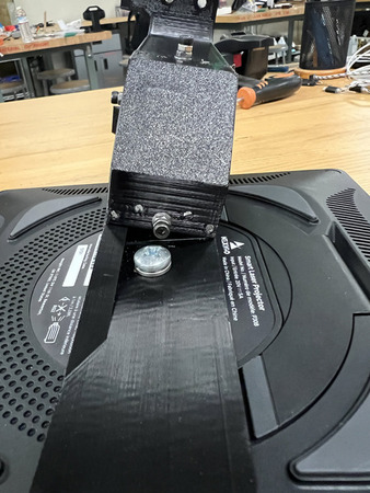
- Install QTY (2) Y Locator underneath the base of the Projector Stand using QTY (2) M5x10 Button Head Screw with QTY (2) Hammer TNut from the counterbores on the Projector Stand (see image for location).
NOTE: The screws in the image are inaccurate, we had to use longer screws due to a misprint. For general case, use M5x10 Button Head Screws.
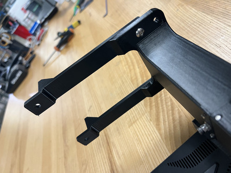
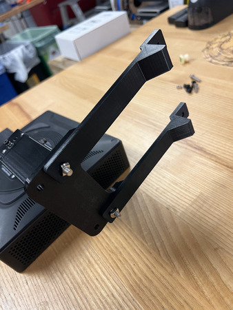
Install QTY (2) M5x10 Button Head Screw with QTY (2) M5 Hammer TNut on the opposite end of the QTY (2) Y Locator.
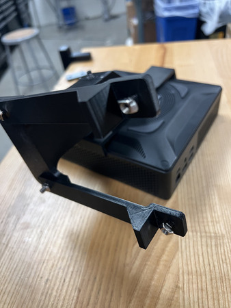
The Projector Mount subassembly is now complete.
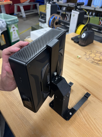
Parametric Design: Different Projector
Note
These instructions are for those who DO NOT use the NexiGo Nova Mini Laser Projector. Using a different projector will result in the following components changing:
Projector Interface
Projector Base
X Locator
Y Locator
Projector Shroud
On Onshape, the currently variable table that would be edited for the Projector Mount can be found by going into the Optics Folder > Projector Mount > Variable Tables (Math) > VALUES USED IN CAD. It is also shown below:
Number |
Name |
Value (Original) |
Description |
|---|---|---|---|
1 |
H_F |
98.5 mm |
Projector’s Mounting Hole (Center) to Front Face of Projector (face with lens). |
2 |
H_S |
98.5 mm |
Projector’s Mounting Hole to the side perpendicular and closest to the front face. |
3 |
L_B |
18 mm |
Center of lens to the bottom of the projector. |
4 |
L_S |
53 mm |
Center of lens to the closest side. |
5 |
Width |
199 mm |
Width of projector perpendicular to the lens. |
6 |
Hole_Size |
6.35mm |
Dimension of mounting hole (most are 1/4 inch). |
7 |
Y_flip |
N/A |
Distance from side of projector mount to center of projector lens.
Only use this measurement if the projector mount needs to be flipped.
See note under image below for further instructions.
|
Images with respect to the table above:
H_F
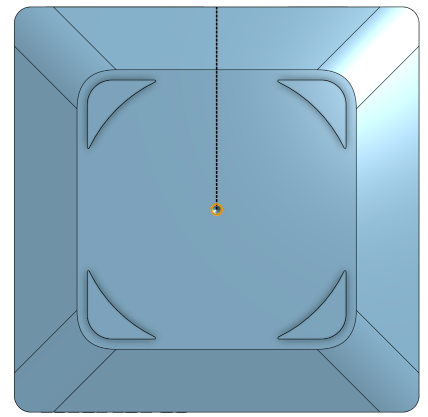
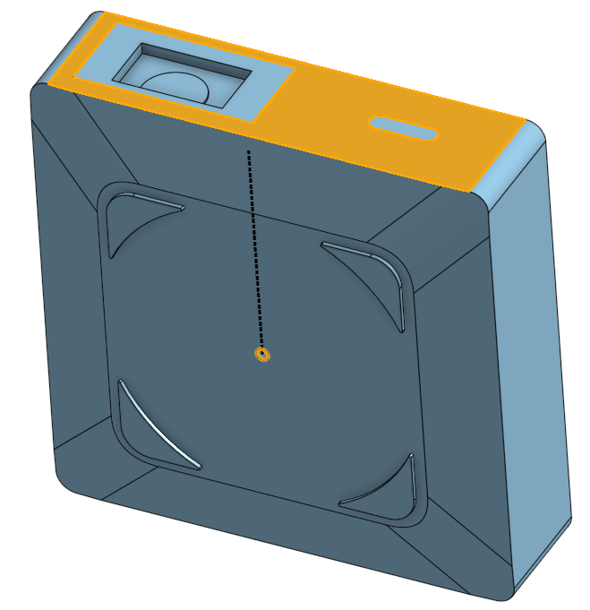
H_S
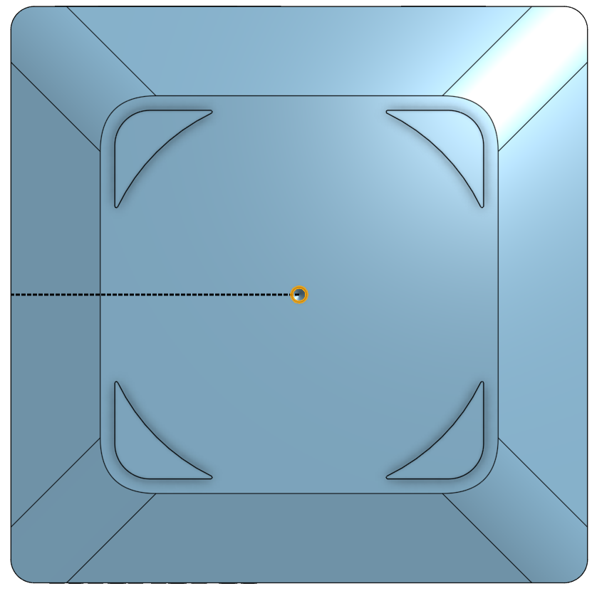
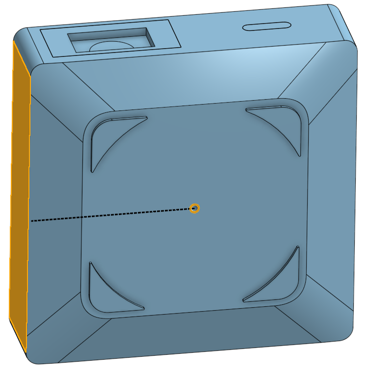
L_B
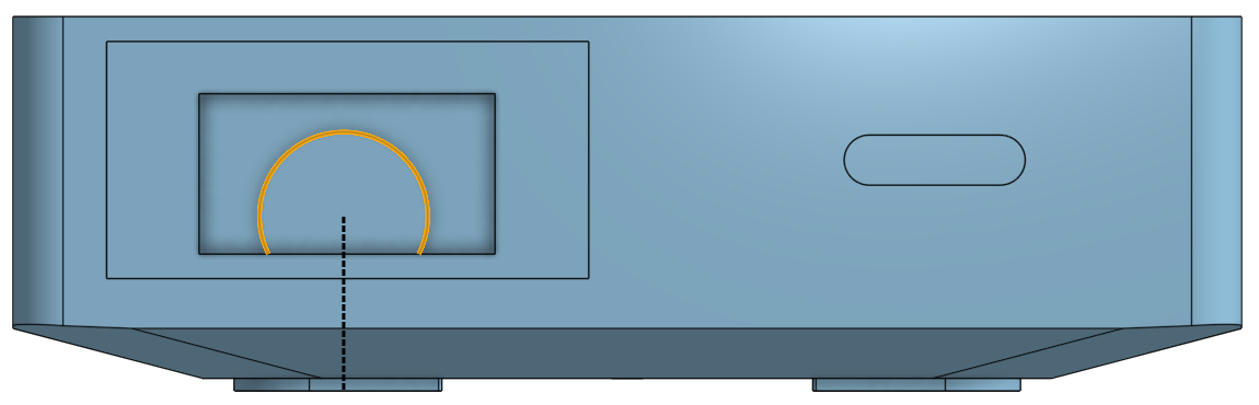
L_S
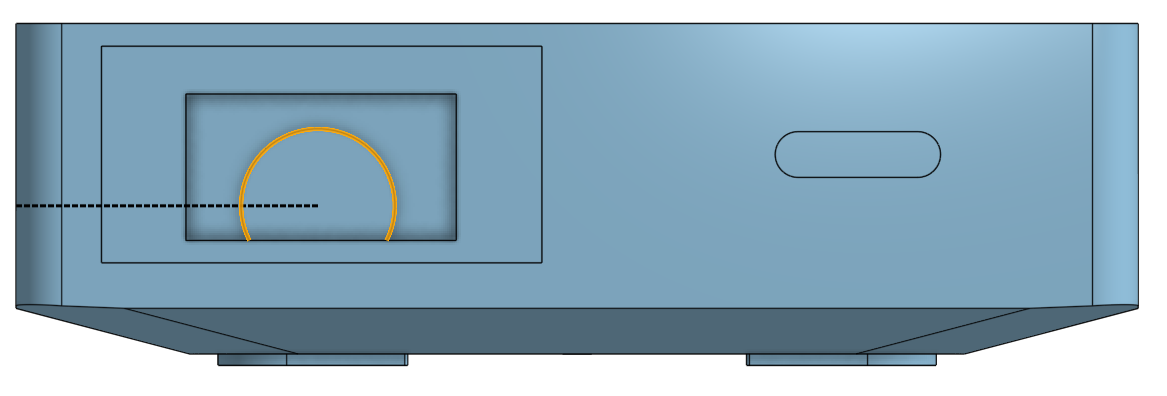
Width
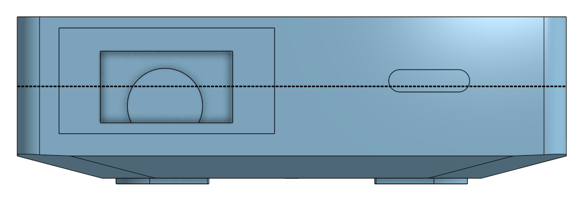
Hole_Size
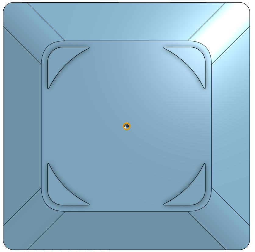
Y_flip
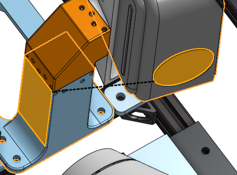
Note
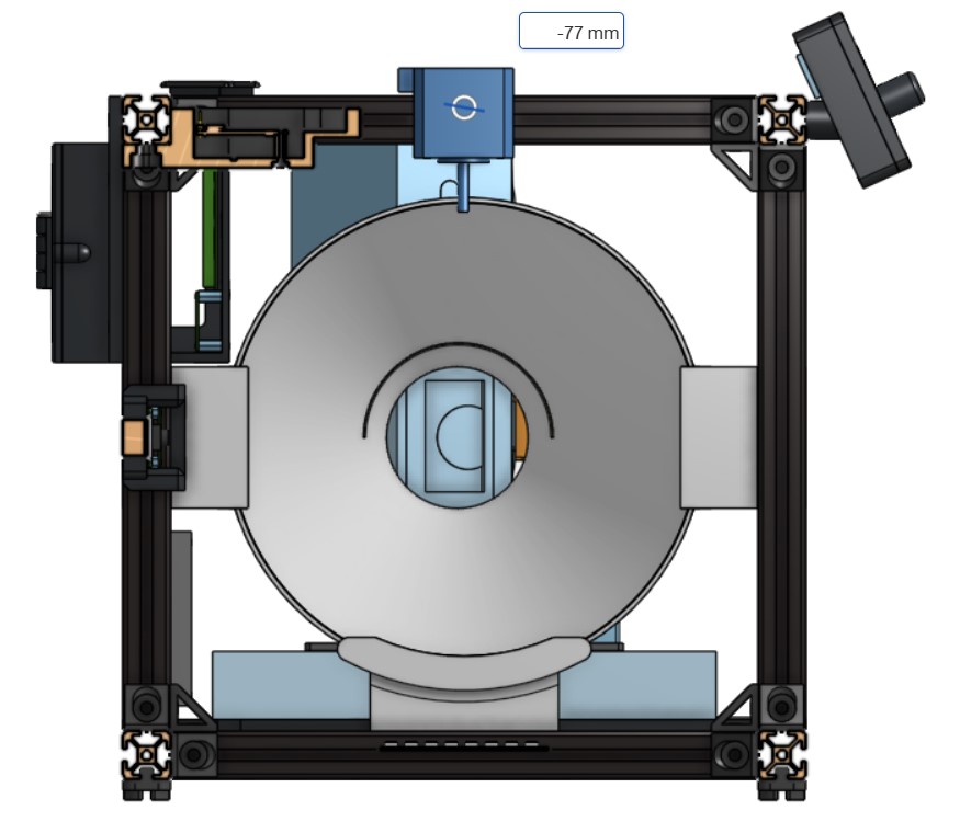
The Y_flip is a rough estimation in the case that the mount has to be flipped relative to the projector (the projector is closer to the front - opposite of our configuration). Thus you would need to add the distance of the projector mount. This drastically changes the distance of the X Locator. For a case where the projector mount is flipped, a new X_flip variable was created in the “VALUES USED IN CAD” table on Onshape. As it is an estimation, you can ensure it is correct by updating the code, ensuring the entire projector mount system is constrained correctly, and seeing if the projector lens is centered relative to the projector shroud and the fresnel lens. See image below. This is how you will ensure that your X locator and other components are correct.
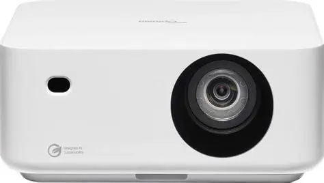
An example of a projector that would use this (and thus have a flipped configuration) is the Optoma ML1080 projector. It can be seen that, compared to our projector, the lens is on the right side rather than the left.
There are two other tables that are dependent on the variables described above. One is the Projector Lens Position Table (which should not be changed):
Name |
Value (Original) |
Description |
|---|---|---|
Lens_Angle |
13.18 deg |
This should be fixed and should not change unless a projector with a different Throw Ratio (1.2:1) is used. |
Y_tot |
405 mm |
Total Length Distance of Projector Area from Inside Rails. This should not be changed as it is based on the Frame dimensions. |
X_tot |
250 mm |
Total Width Distance of Projector Area from Inside Rails. This should not be changed as it is based on the Frame dimensions. |
Y_tot
X_tot
The other is the VALUES USED IN CAD Table (which also should not be changed):
Name |
Value (Original) |
Description |
|---|---|---|
Col_Lens |
176.6 mm |
IMPORTANT: This is the ideal distance between the lens of the projector and the fresnel lens.
Theoretically, this is based on simulations and an ideal equation. However, we were not able to find the exact
correct equation. Thus, this is a hard value that we measured in person after finding the correct distance for
collimation. This variable is important as it defines the Y variable below which sets the length for the Y Locator.
|
X |
120.067 mm |
Equation: X = (X_tot/2) + L_B*cos(Lens_Angle) - H_F*sin(Lens_Angle) |
X_flip |
N/A |
Only use this if the projector mount is flipped relative to our configuration.
Equation: X_flip = X + Y_flip
|
Y |
128.39 mm |
Equation: Y = Y_tot - (Col_Lens + L_B*sin(Lens_Angle) + H_F*cos(Lens_Angle)) |
Z |
170.5 mm |
Equation: Z = 125 - L_S + H_S |
Width_Interface |
201 mm |
This is to add tolerance to the Projector Interface so that the projector fits.
Equation: Width_Interface = Width + 2
|