Wiring
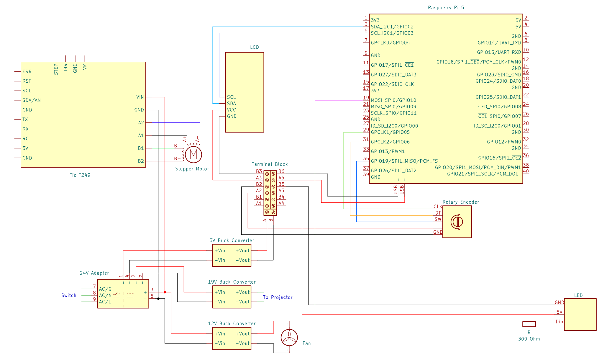
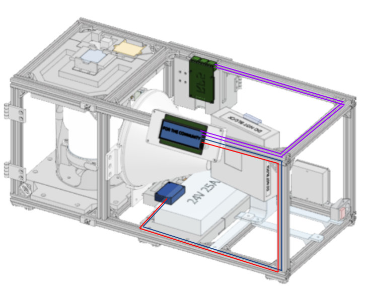
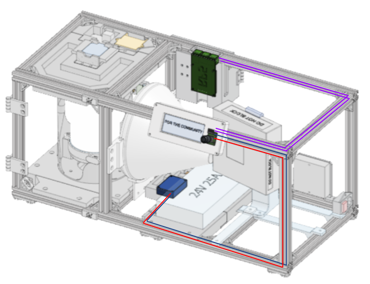
General wiring diagram
Introduction
Required Materials:
26 AWG, 22AWG, 18AWG wire
Heat shrink
Quick disconnect plugs
JST connectors
2.54mm pitch Dupont Connector Kit
4.8mm quick disconnect plugs
Ring Connectors 5.3mm ID
Perf board
8x1 Header Pins x2
HDMI 0.5ft
Zip Ties
Required Tools:
Soldering iron & solder
Dupont crimping tool
Heat gun
References for wiring techniques:
NOTE: The provided wire lengths are an approximation. For cleaner routing and to account for any differences in your OpenCAL build, measuring wire based on the distances between components in your system.
This guide assumes Main Assembly Process - Part 1 has been completed.
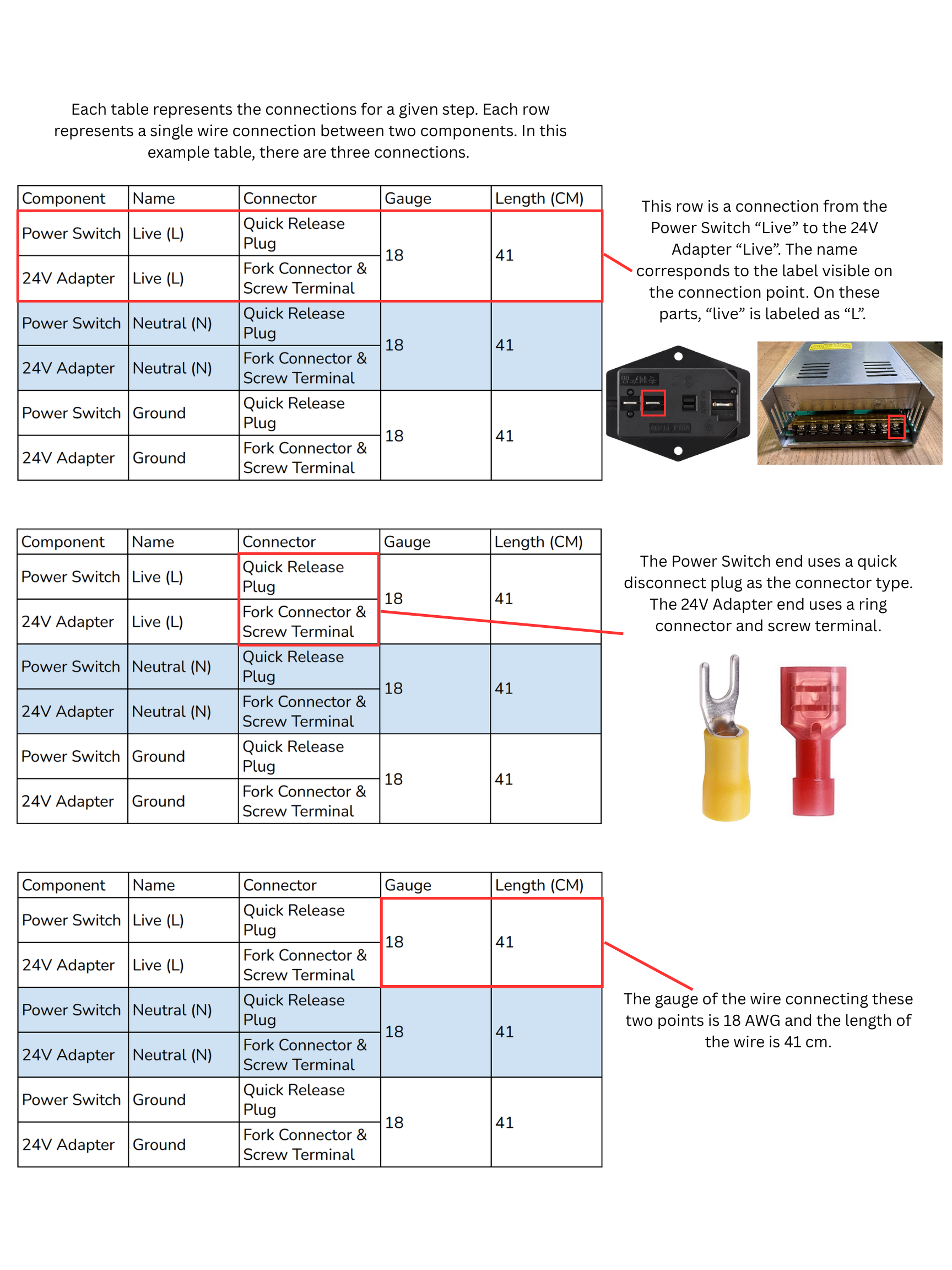
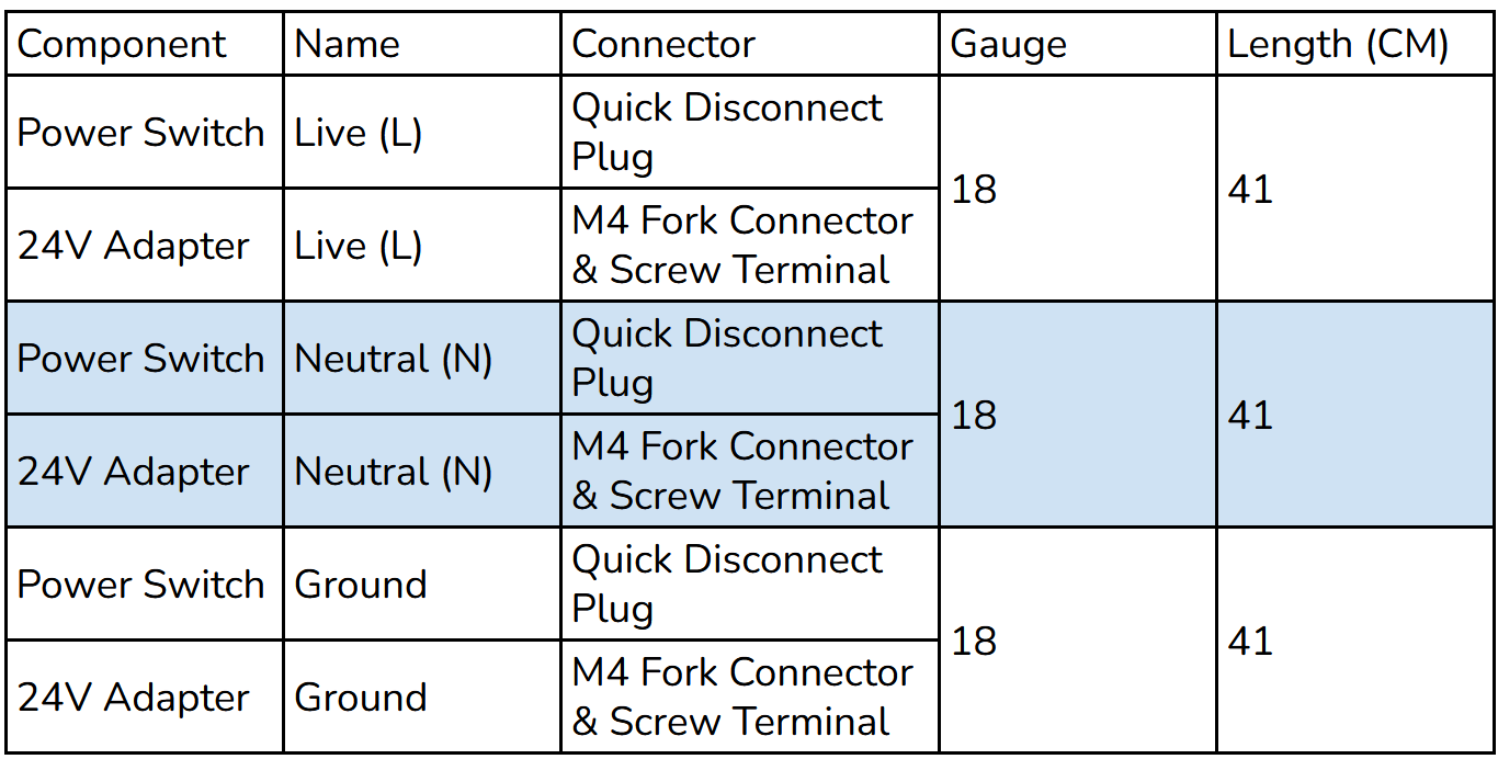
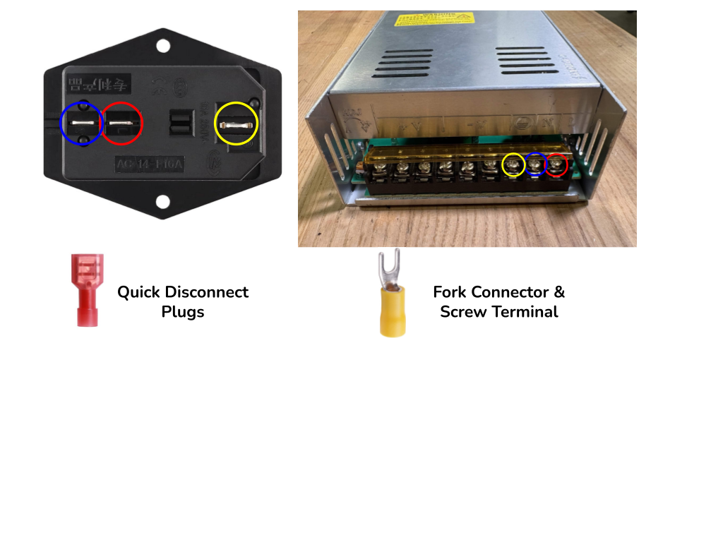
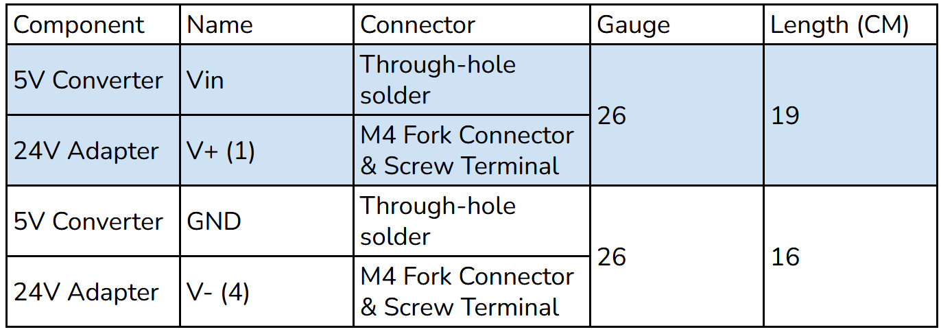
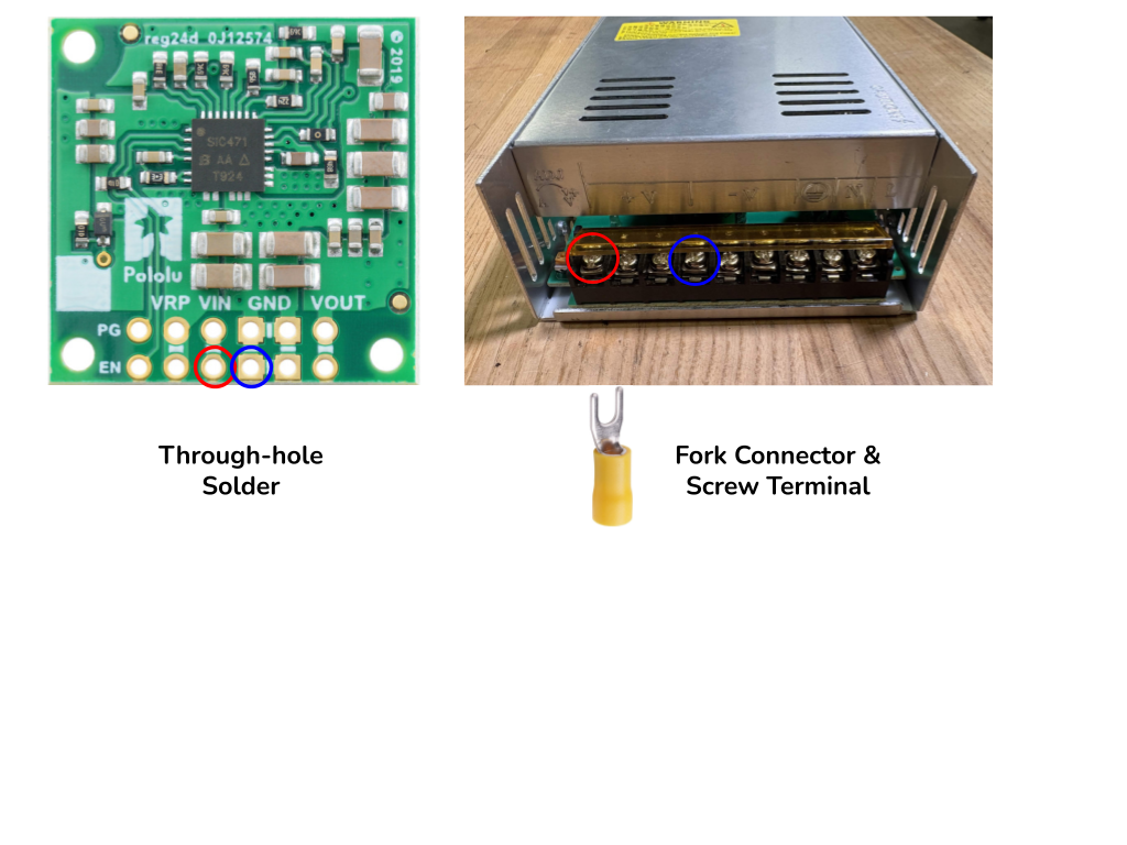
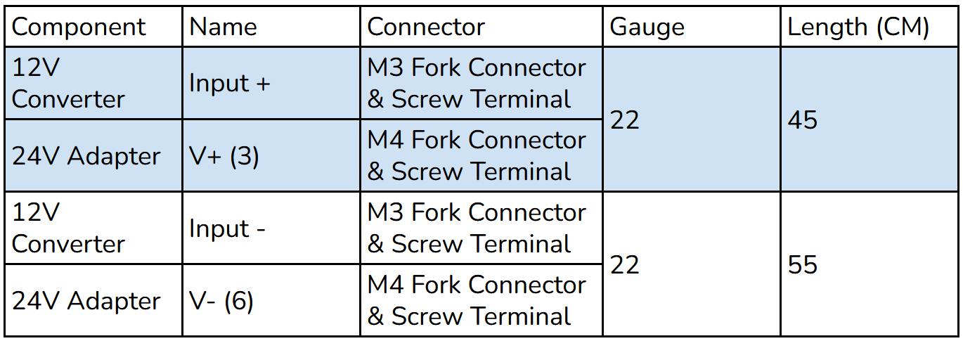
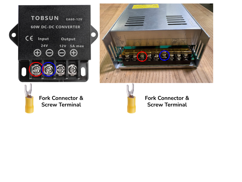
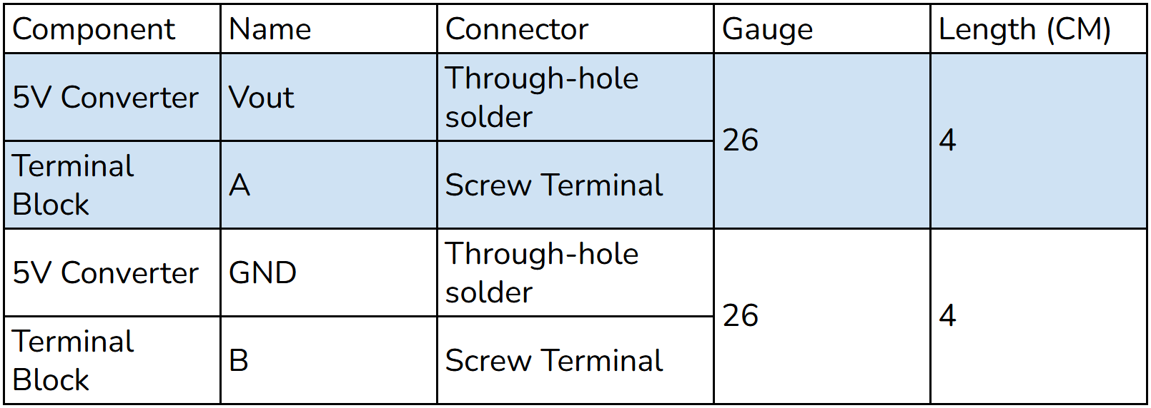
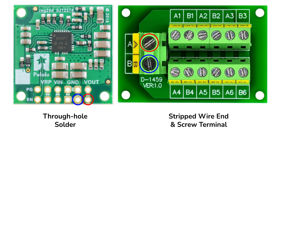
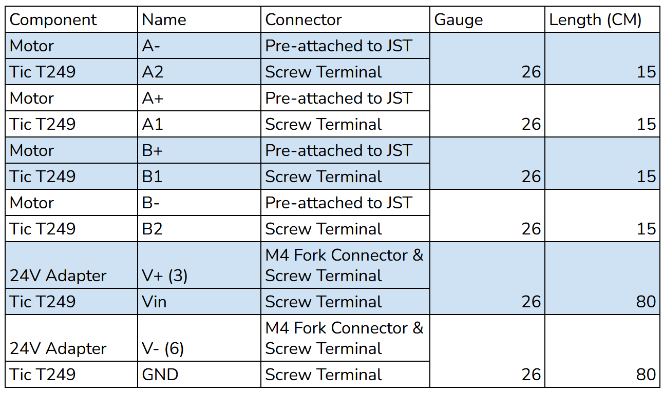
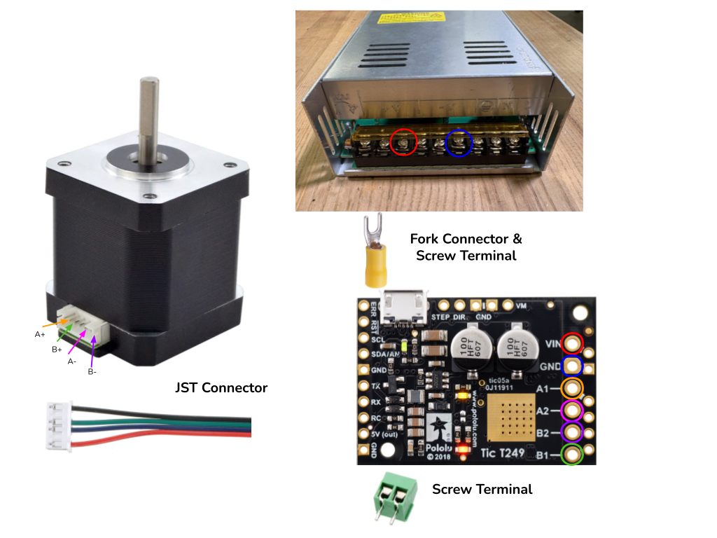
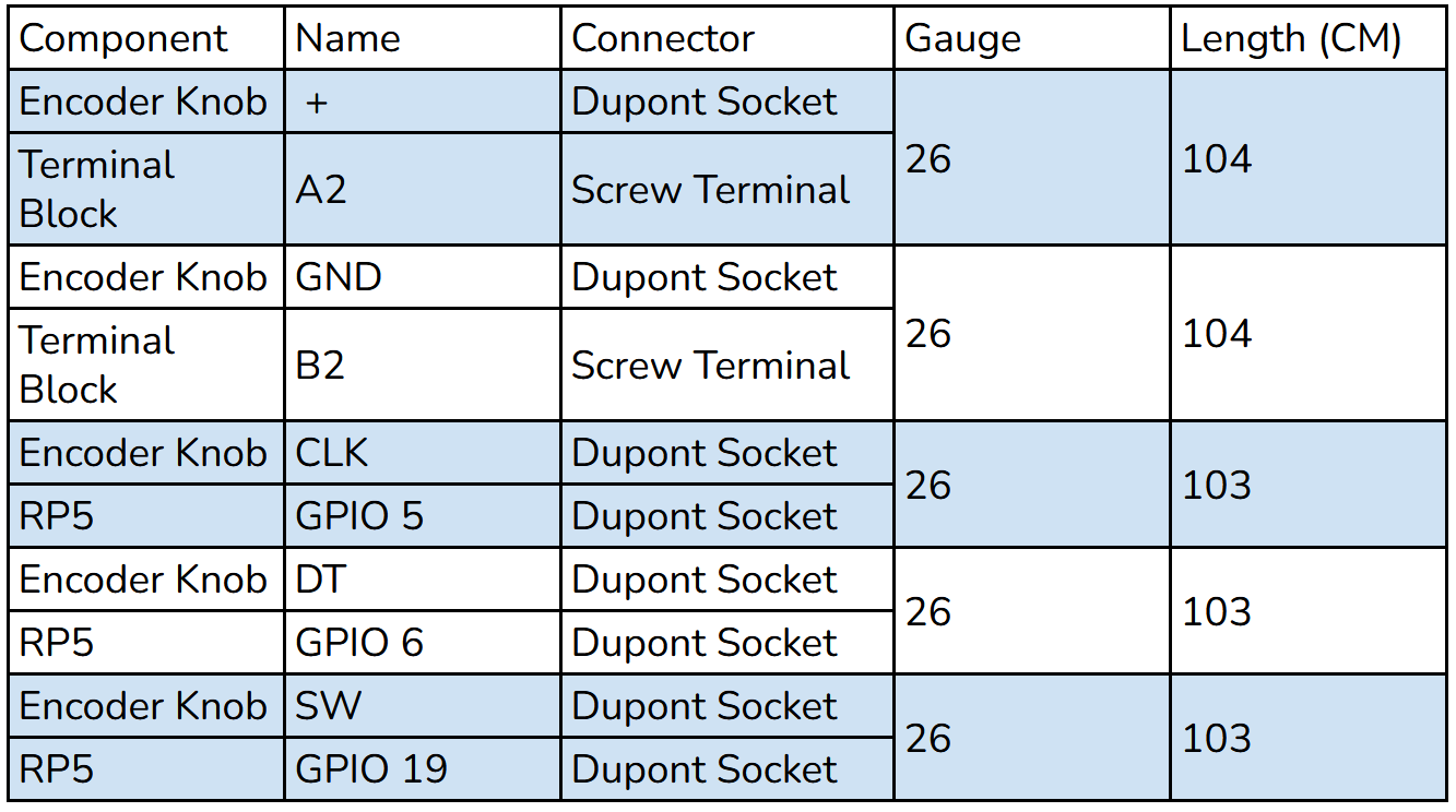
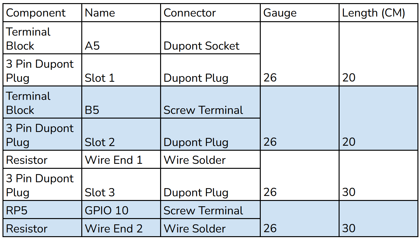
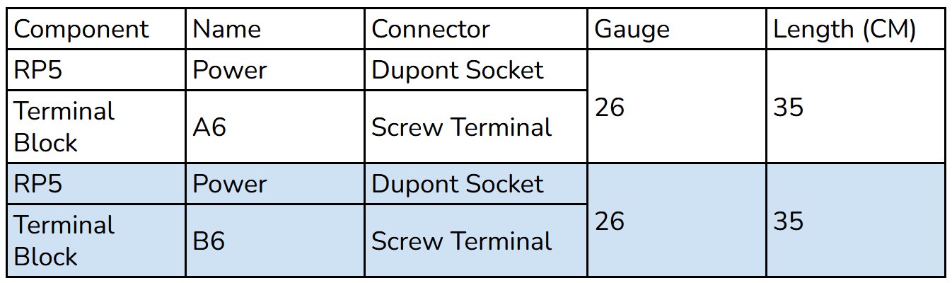
How to Read Wiring Guide Tables
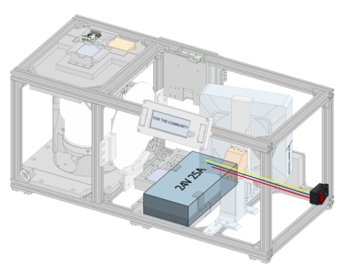
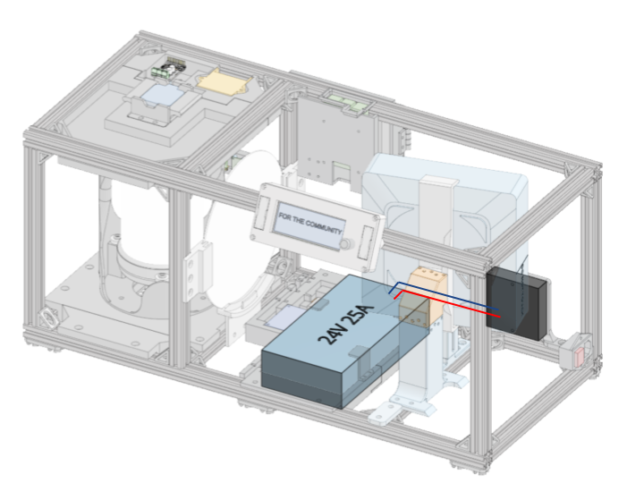
Power Distribution
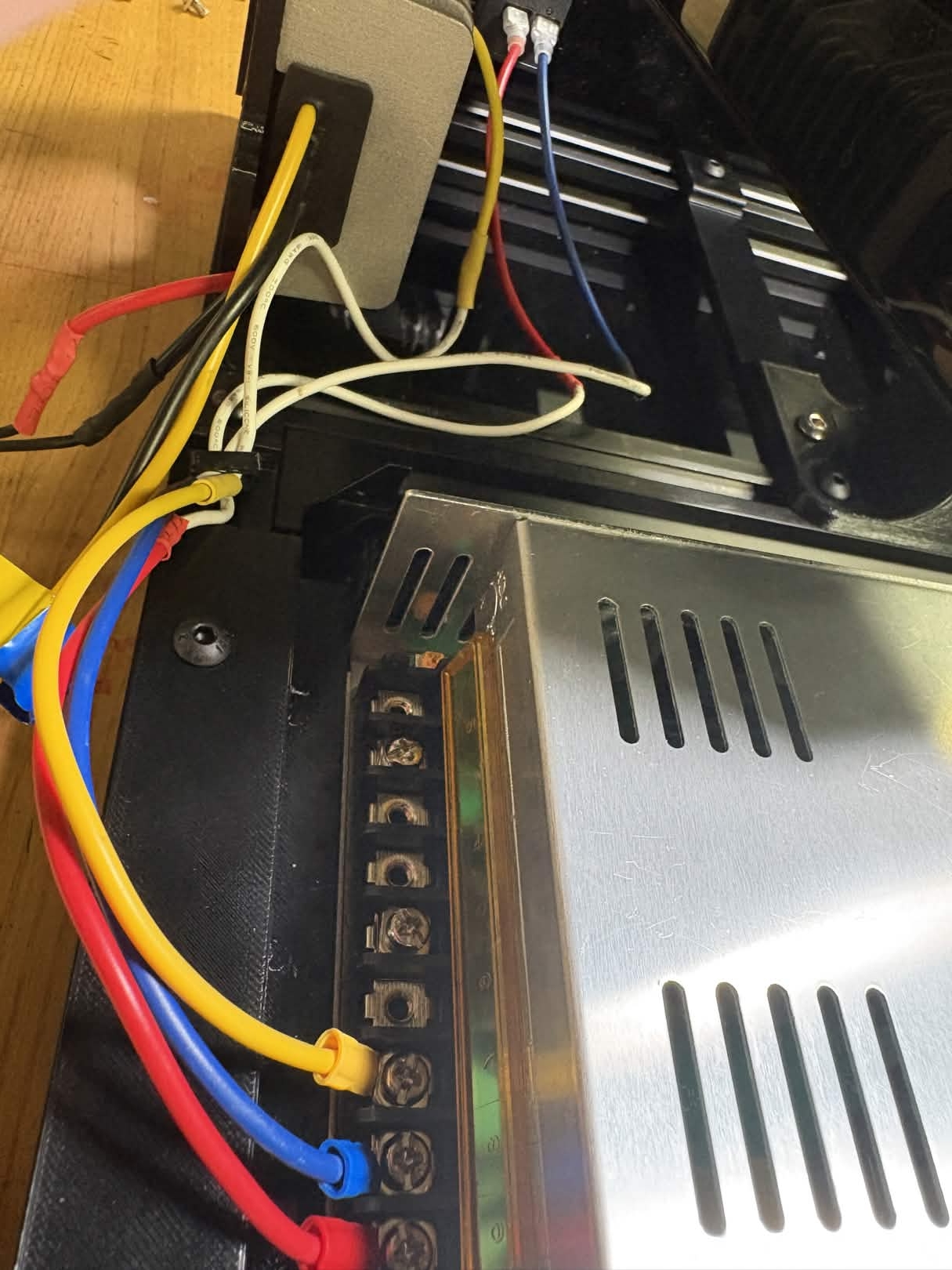
Connect the Power Switch to the 24V Adapter. Use cable clips to secure wire to the 20x20.
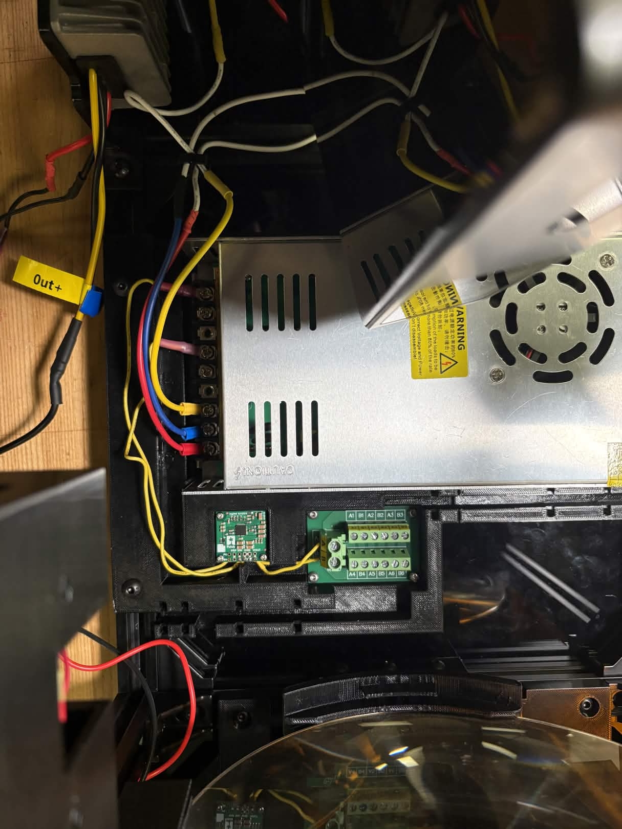
Connect the 5V Converter to the 24V Adapter. The 5V Converter will need to be removed from the plate to connect wires to the soldering through holes, then reattached.
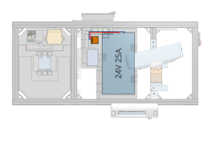
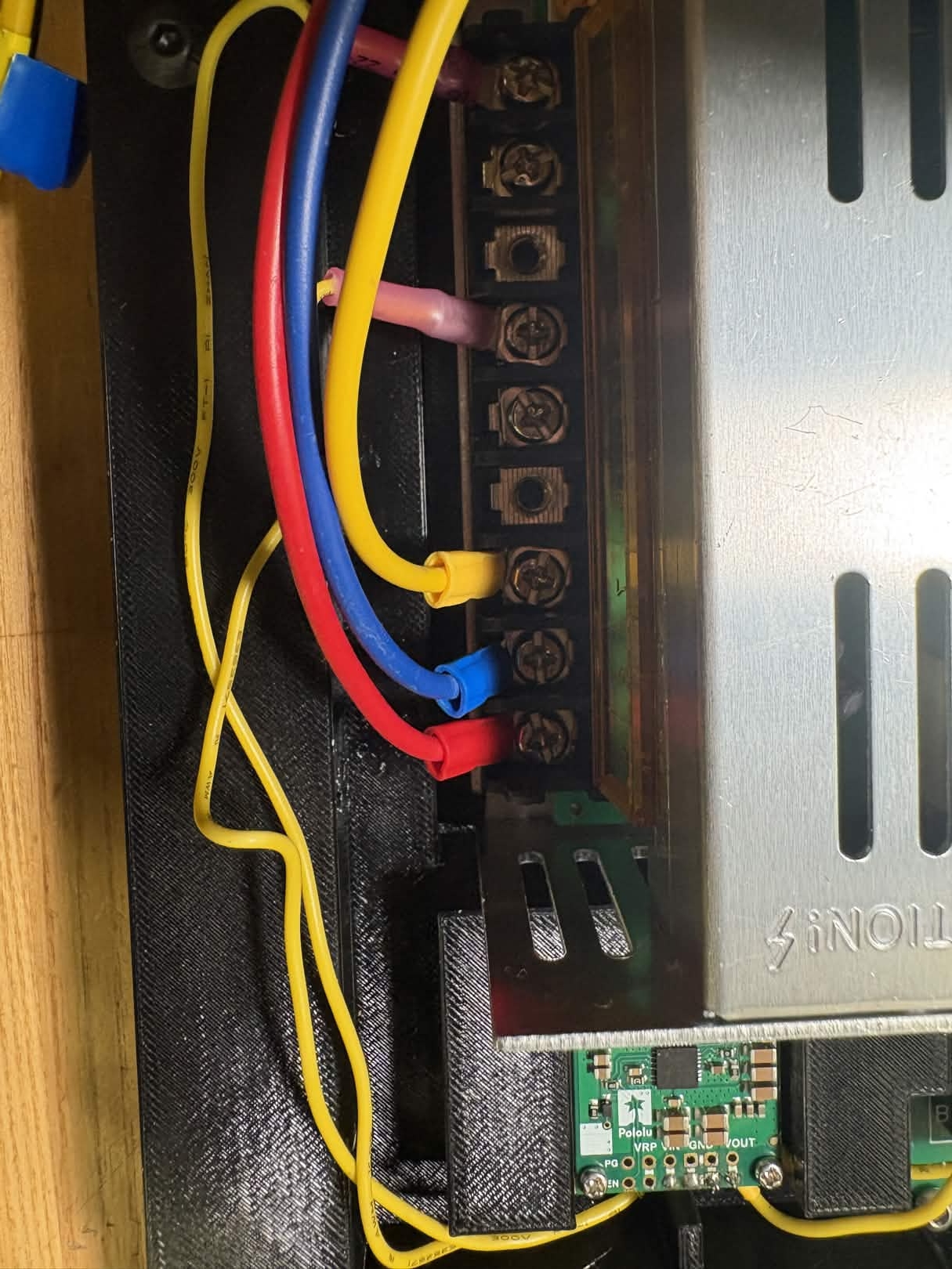
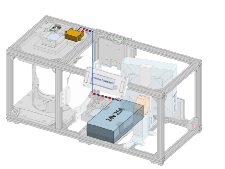
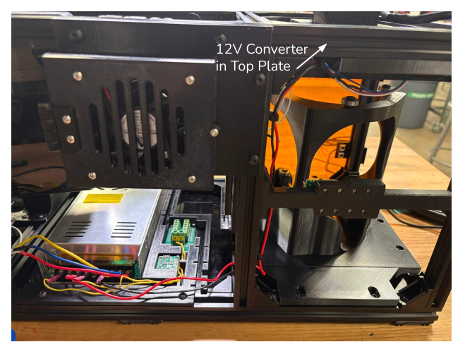
Connect 12V Converter to the 24V Adapter. Use cable clips to secure wire to the 20x20.
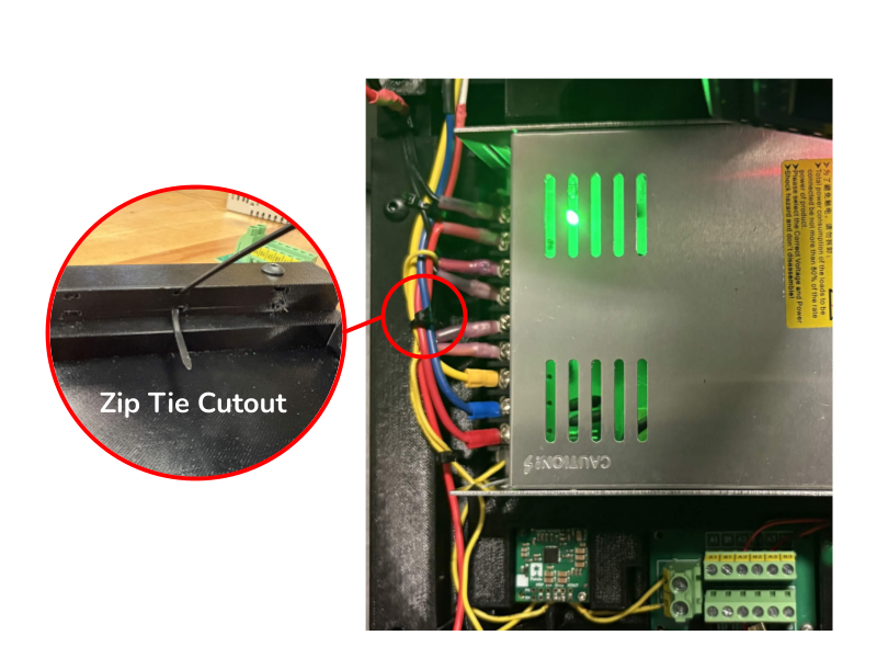
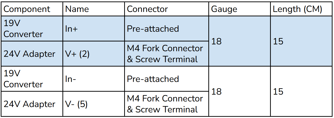
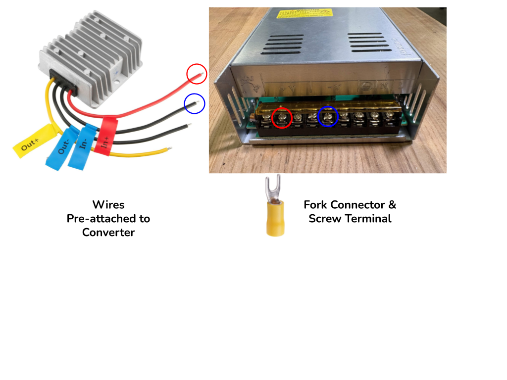
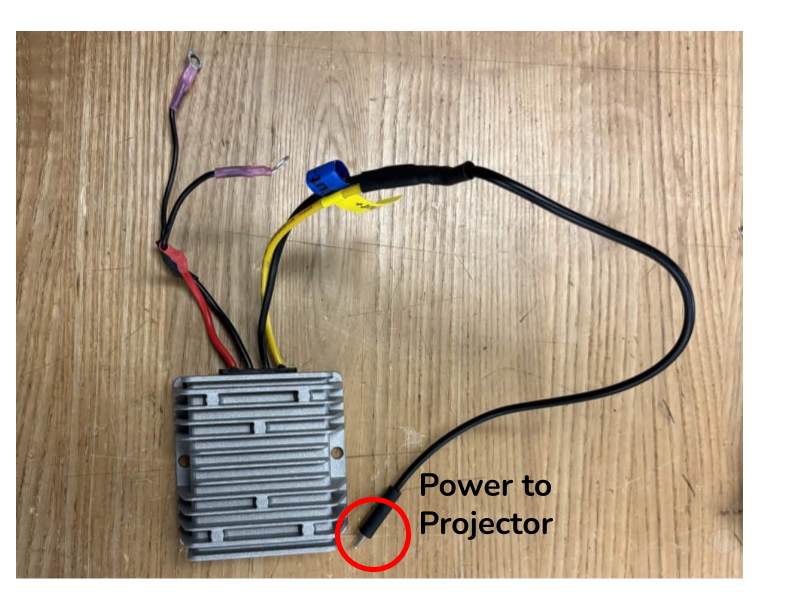
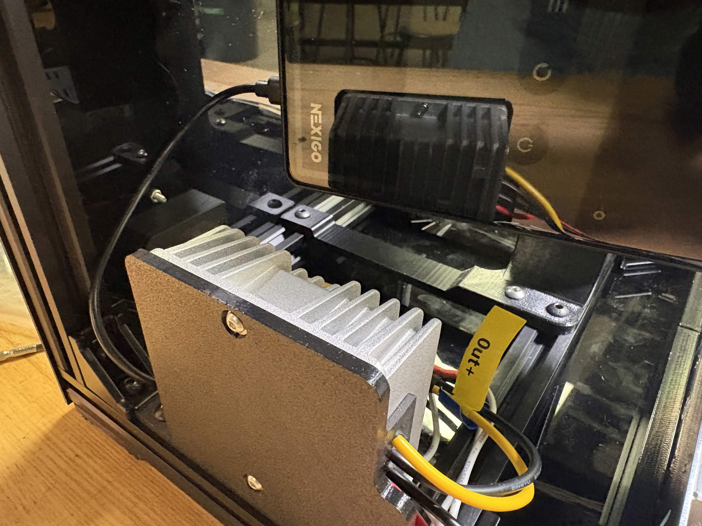
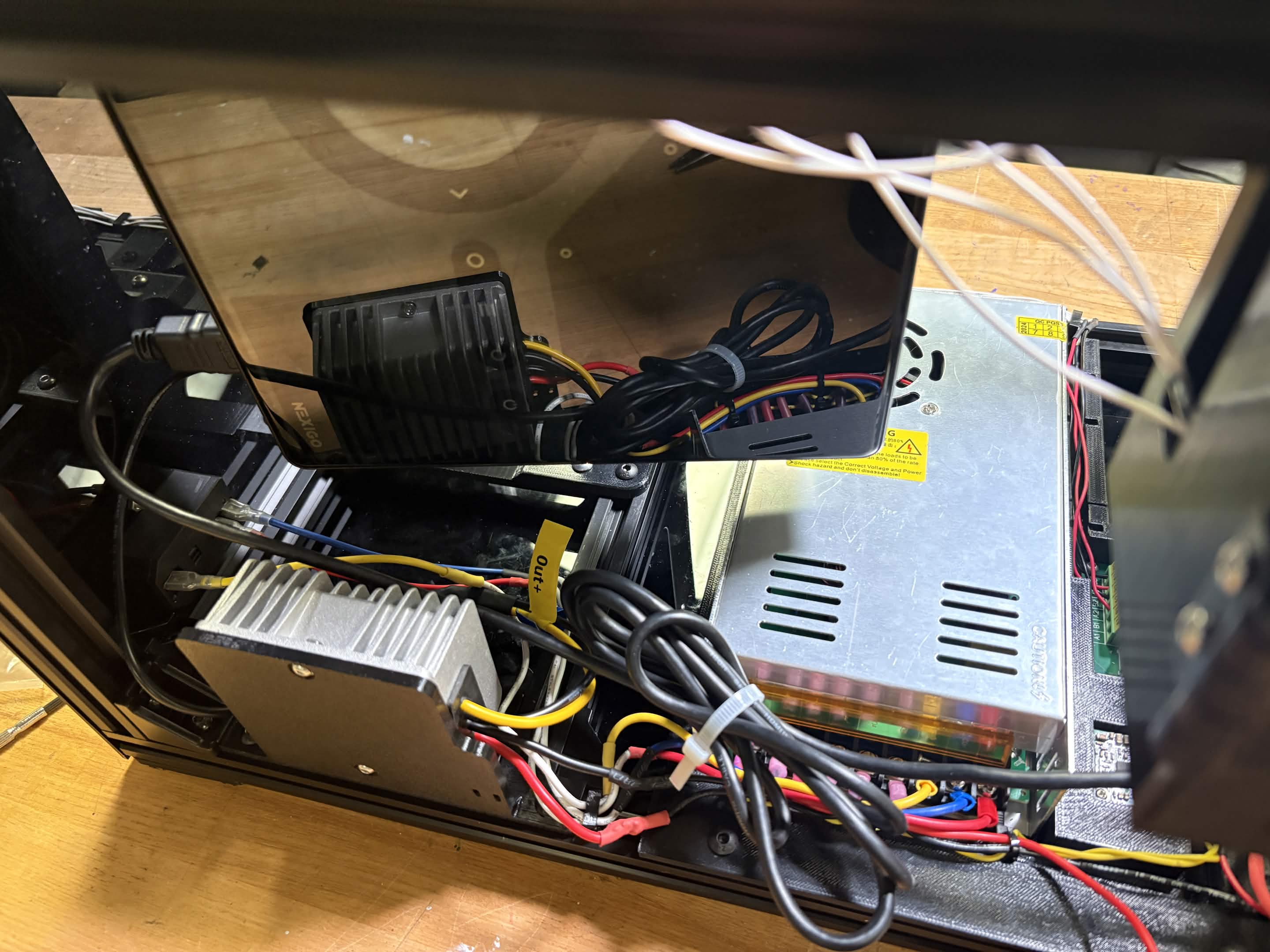
Connect 19V Converter to the 24V Adapter. Use the zip tie cutouts to secure wires in front of the 24V Adapter. Note: If you are using a different projector, the voltage requirement may be different from 19V. Check power requirements in the product spec and use a different buck converter if needed.
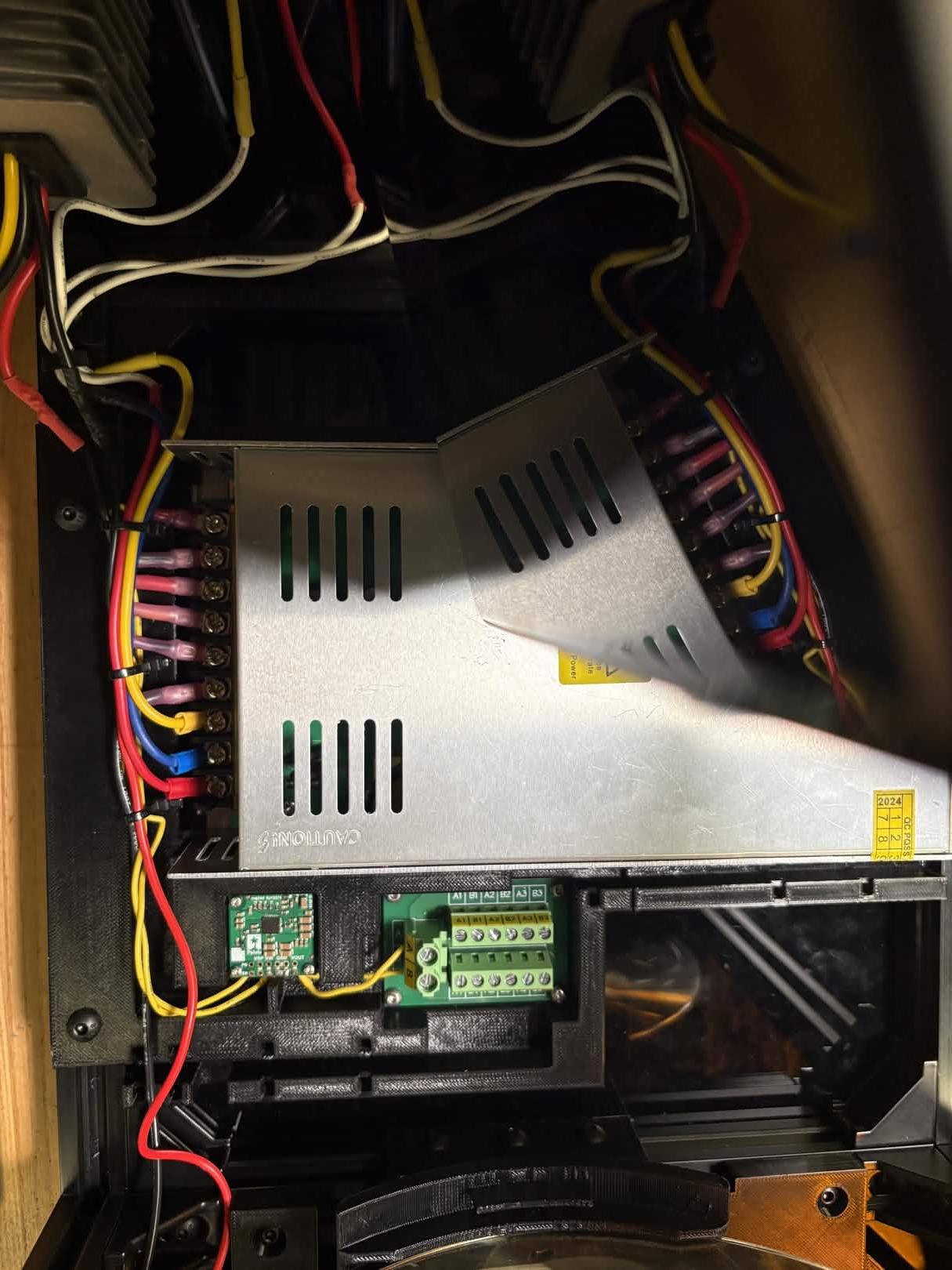
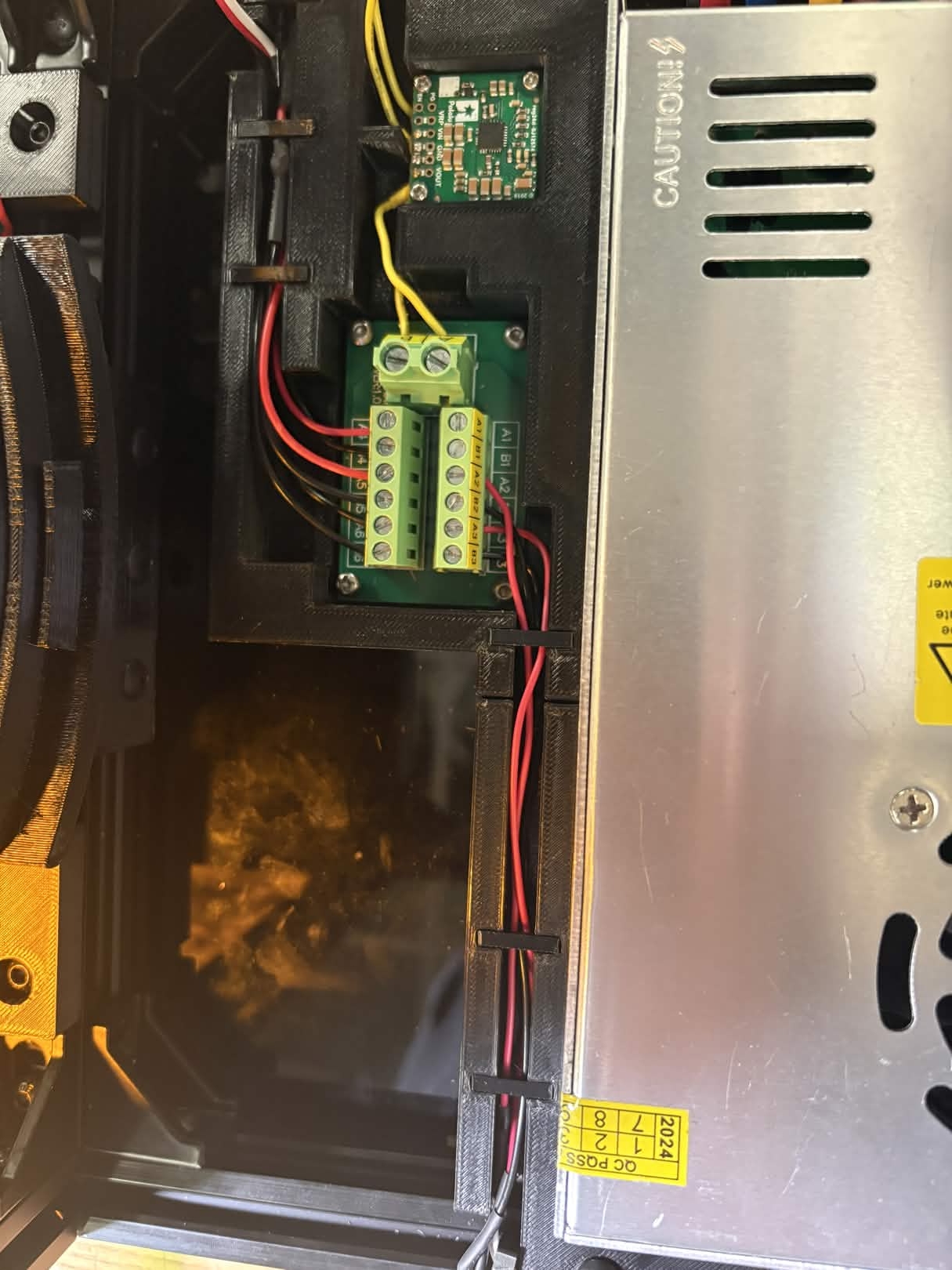
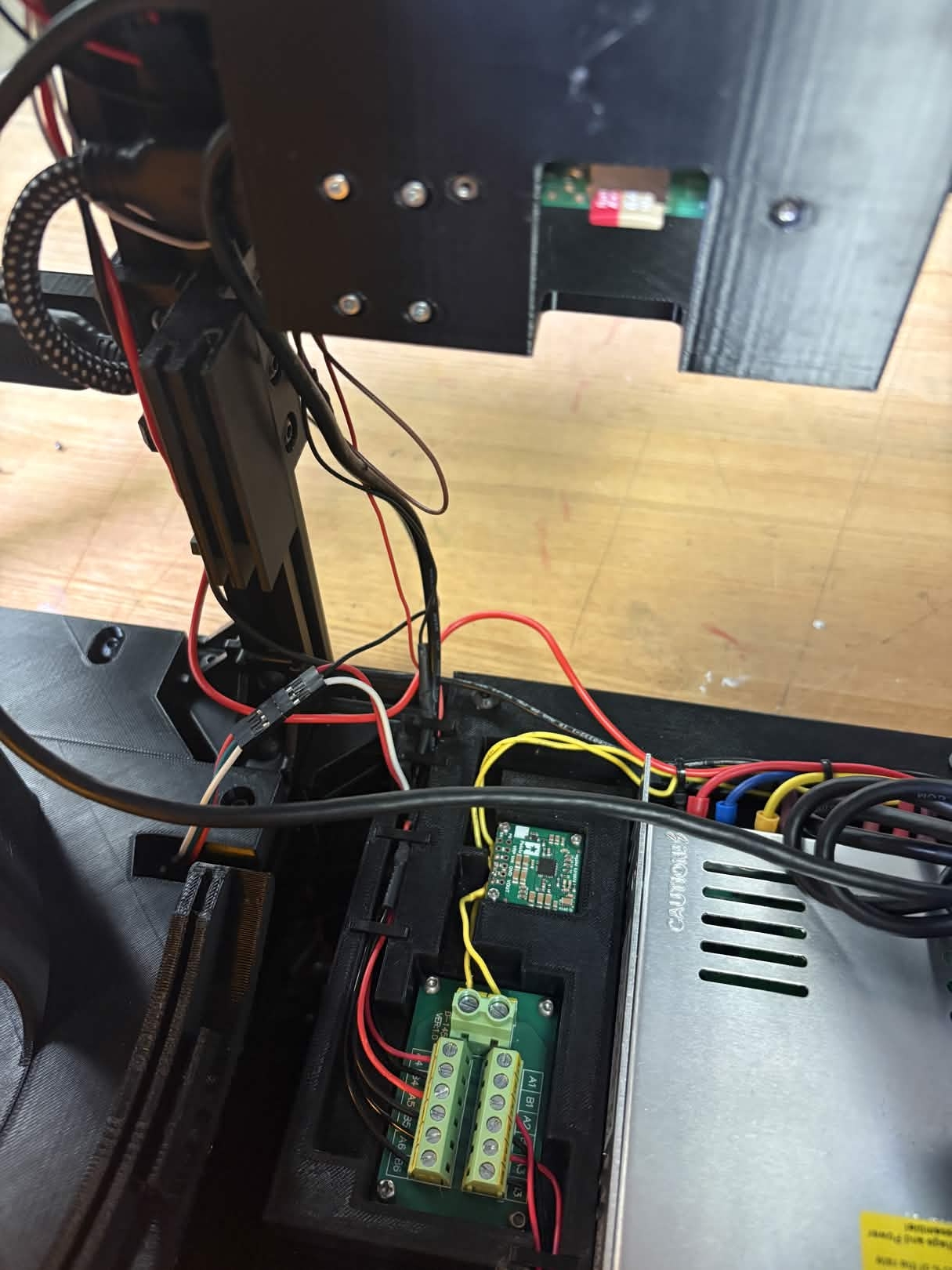
Connect 5V Converter to the Screw Terminal Block, with Vout connected to A and Ground connected to B. This is where all 5V powered components will be connected. It may be easier to remove the Screw Terminal Block from the housing plate while connecting wires. After this step, the 5V Converter requires no more soldering and can be reattached to the housing plate.
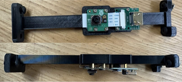
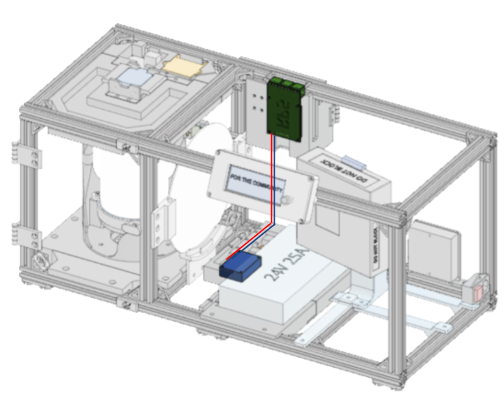
Top Plate Housing Connections
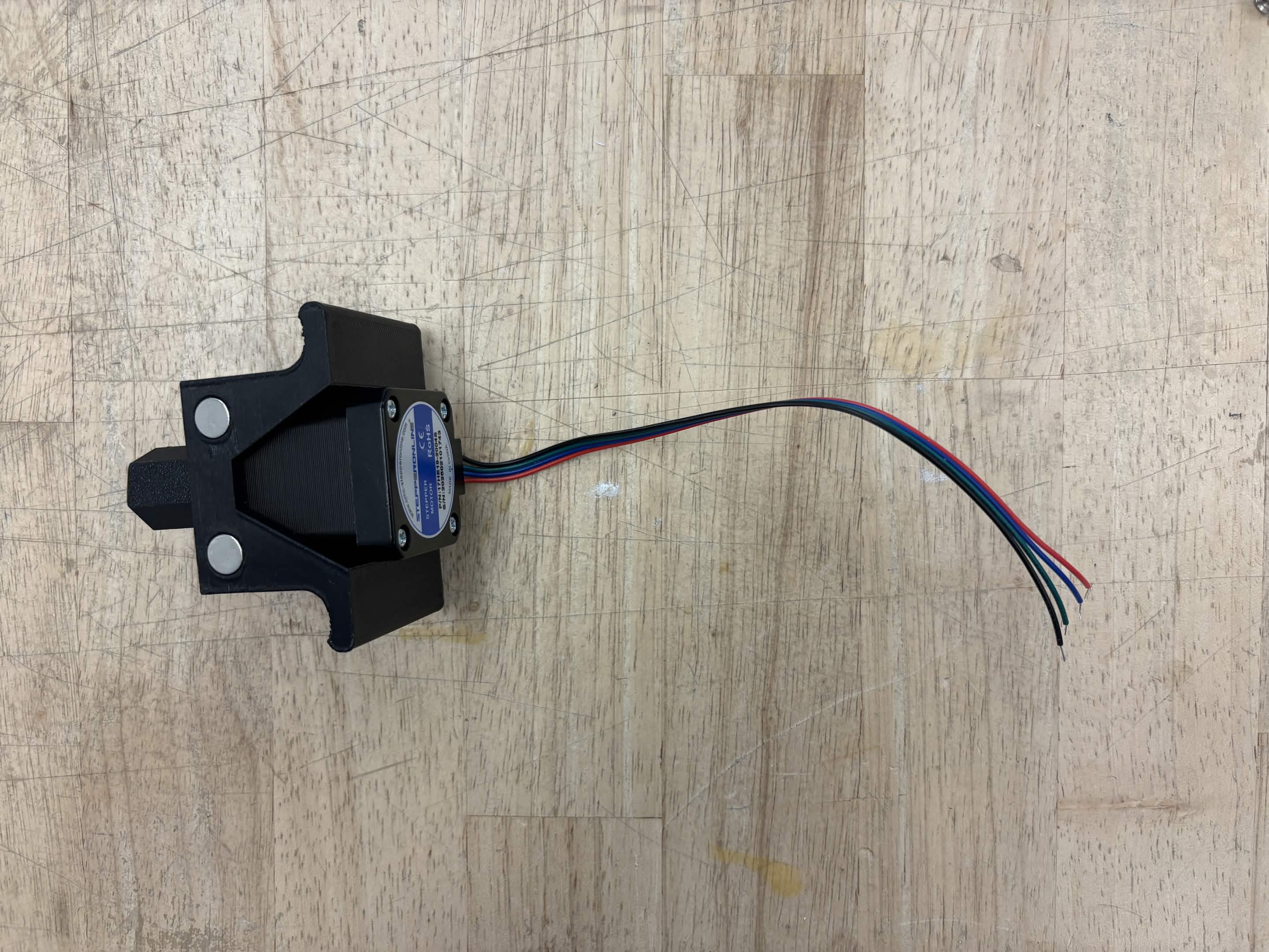
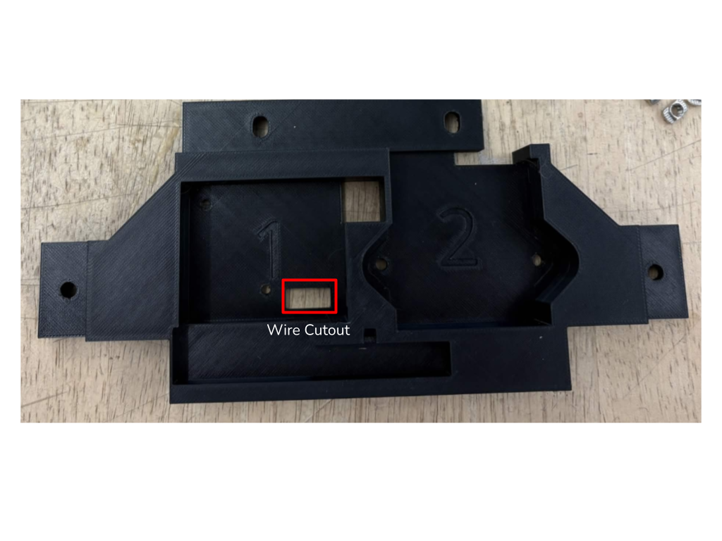
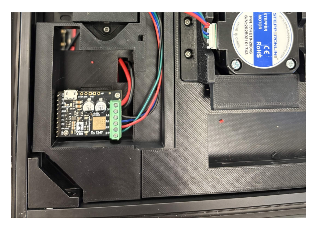
Remove the motor from the top plate. Attach A+, A-, B+, and B- motor wires to the Tic T249 by trimming the provided cable and stripping the ends. Run wires from the Tic T249 to the 24V adapter using the corresponding cutout.
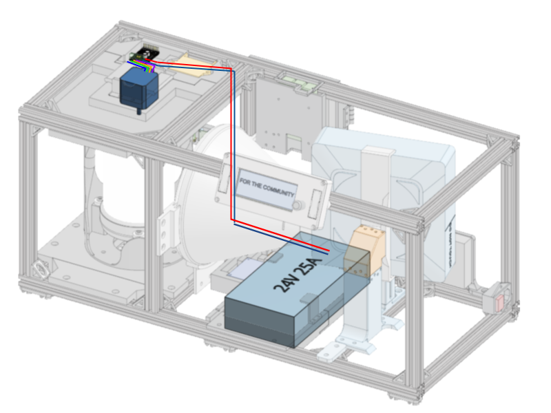
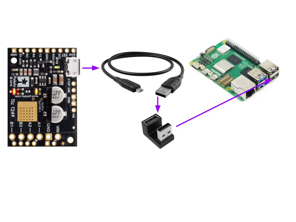
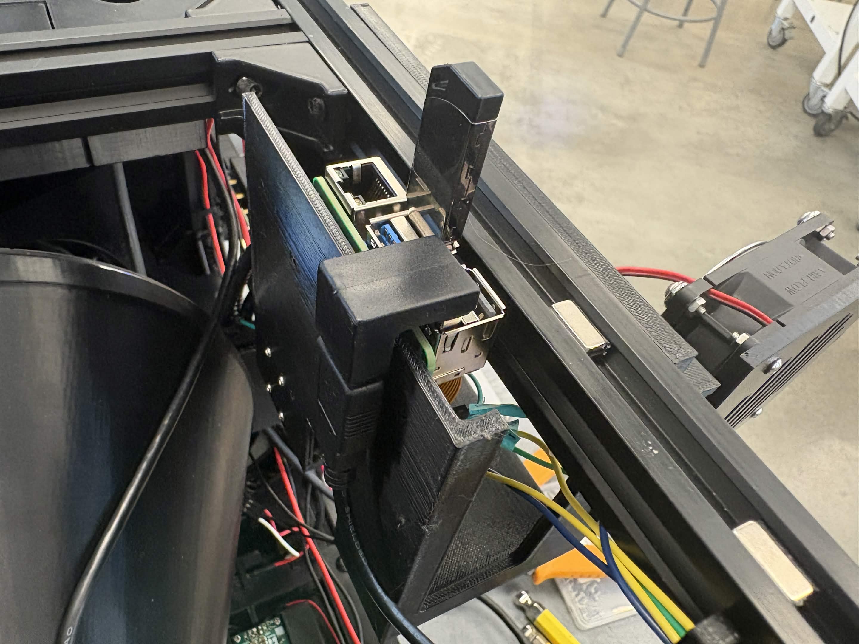
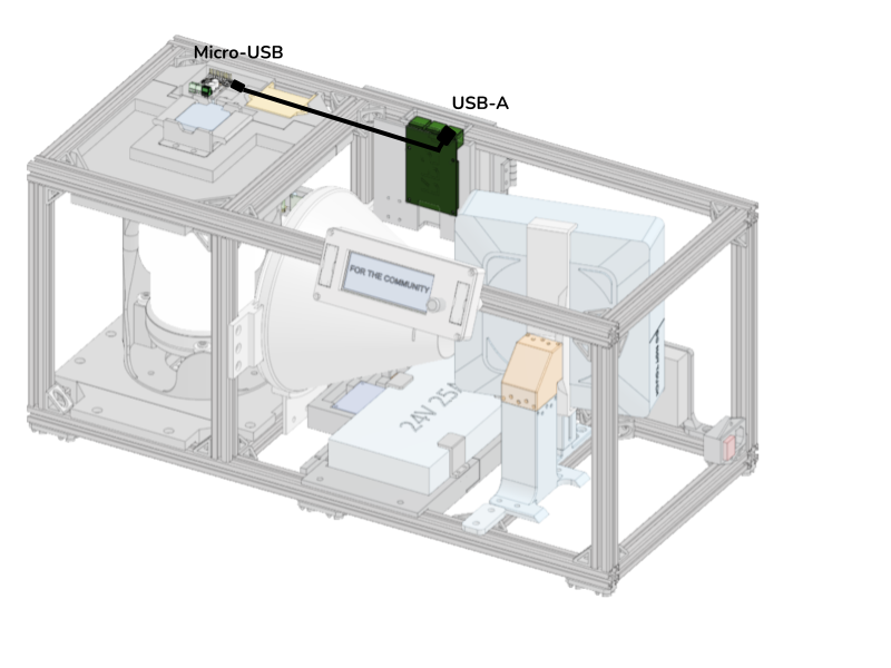
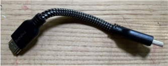
Run a Micro-USB to USB-A cable from the Tic T249 to the RP5 using the designated cutout. Plug the cable into the RP5 using a U-shaped adapter.
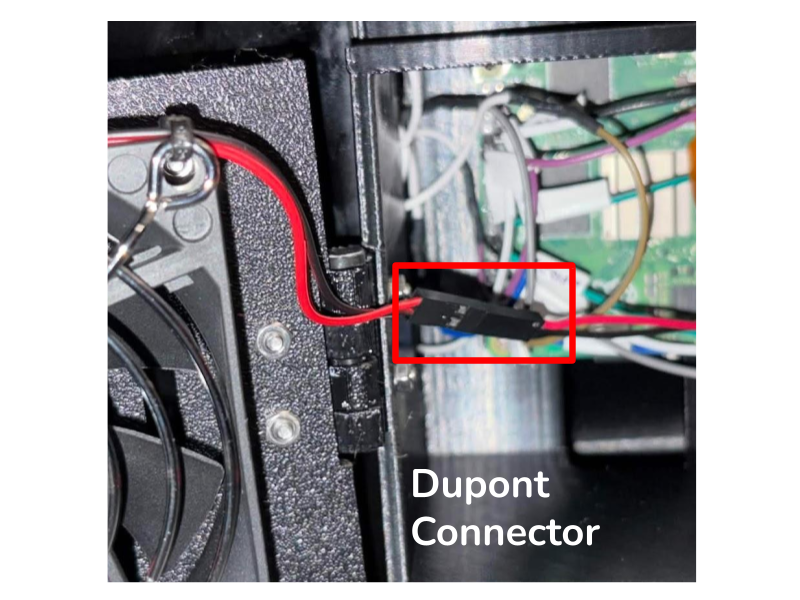
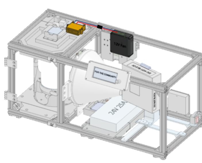
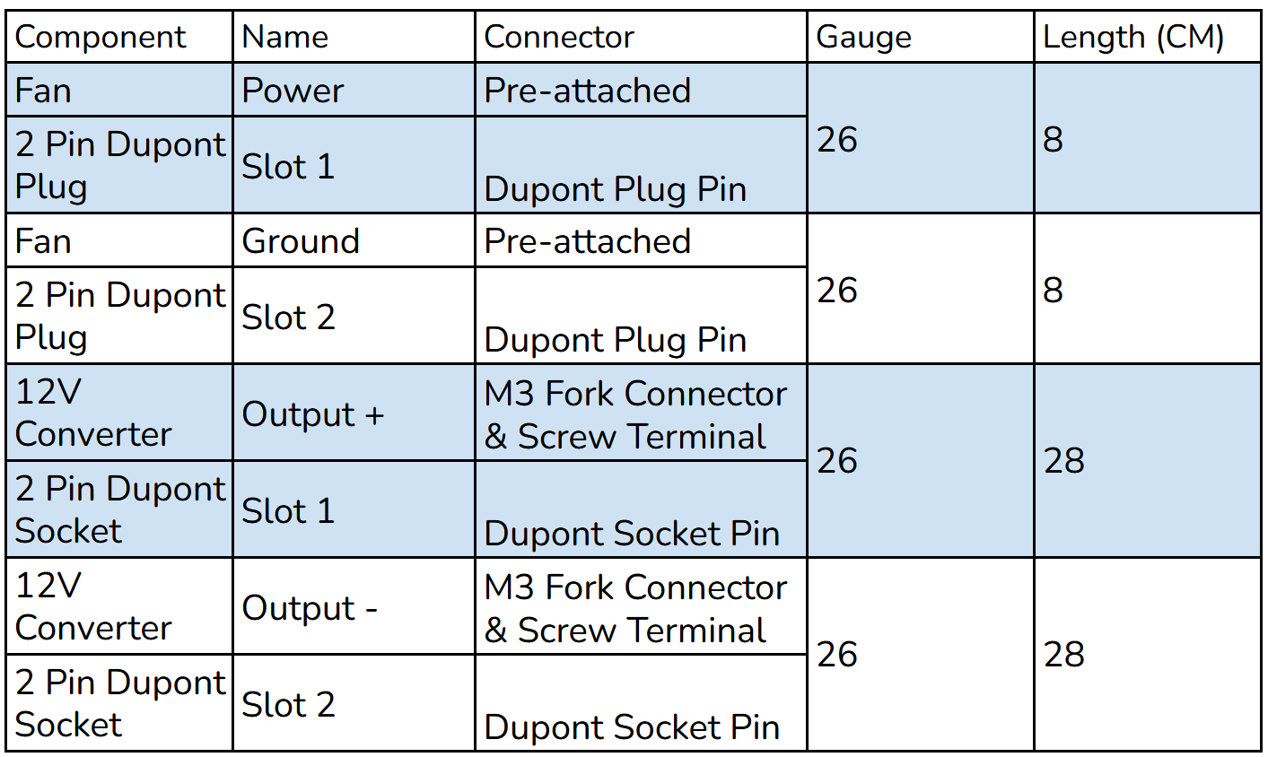
Connect wires from a 2 pin JST plug to fork connectors for the 12V Converter output screw terminals. Ensure Output + and Output - on the 12V Converter correspond to VS and GND on the stepper driver perf board. Use a set of 2 pin Dupont connectors in-between for easy fan removal. Run the wires through the corresponding opening in the Top Plate Housing and through the side of the RP5 housing. Use cable clips to secure wire to the 20x20.
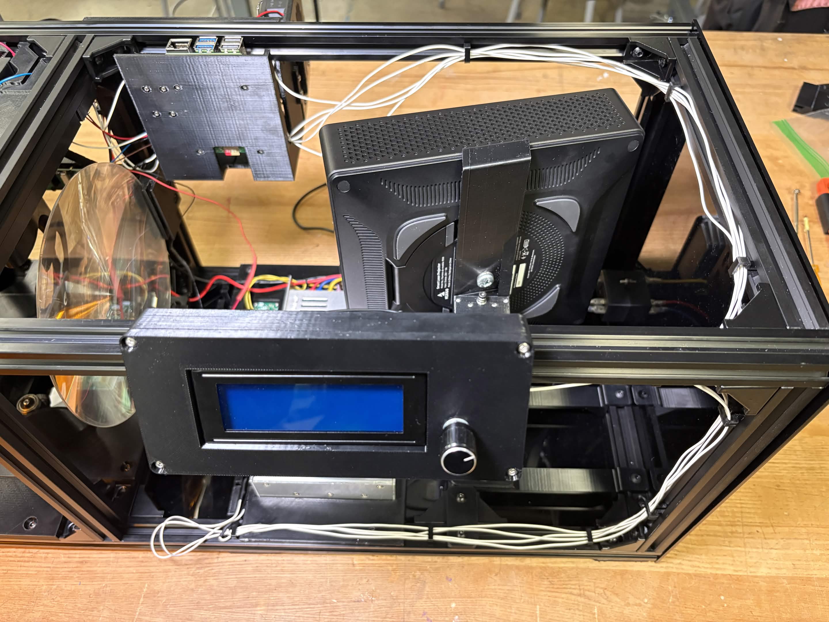
LCD Housing
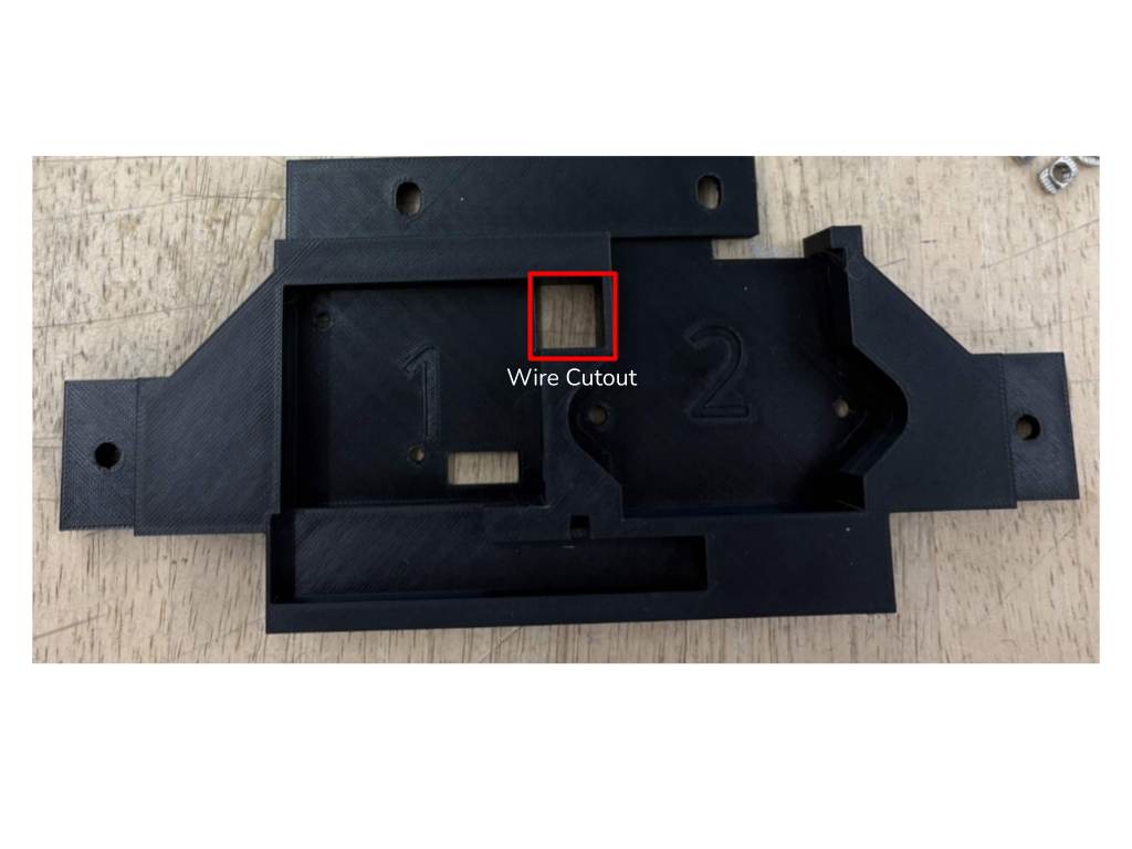
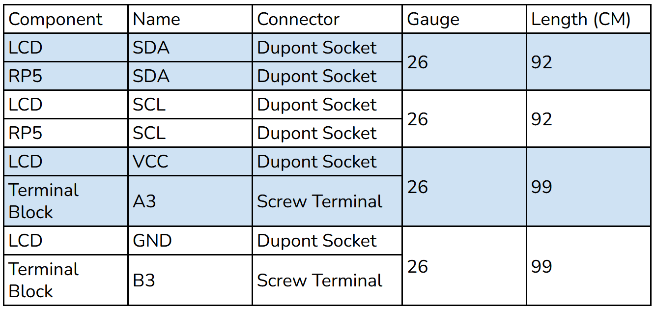
Connect the LCD to the Terminal Block and RP5. Run wires through the cutout in the LCD Housing Mount.
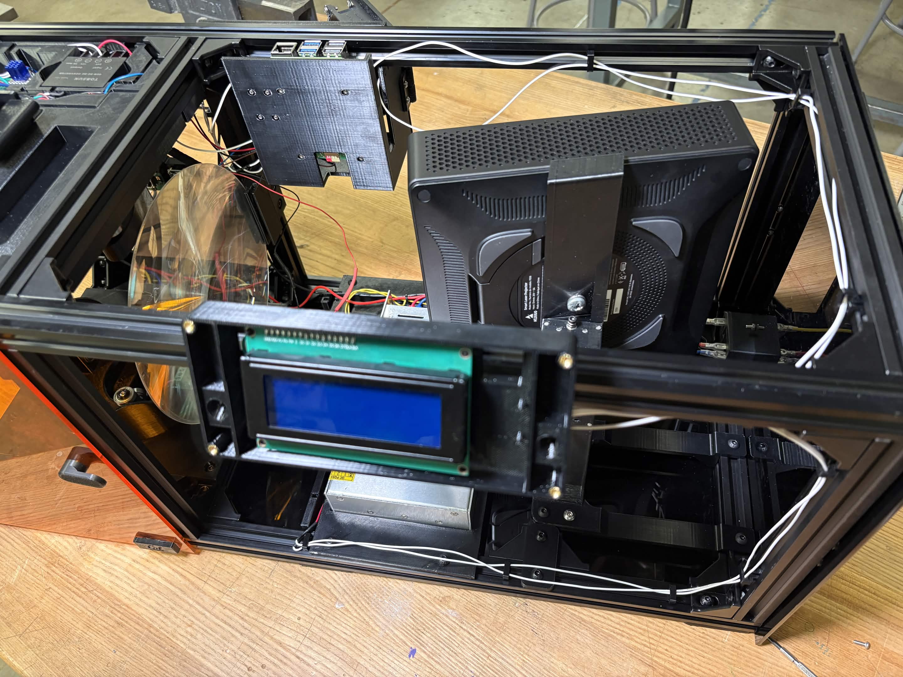
Connect the Encoder to the Terminal Block and RP5. Run wires through the cutout in the LCD Housing Mount.
LED
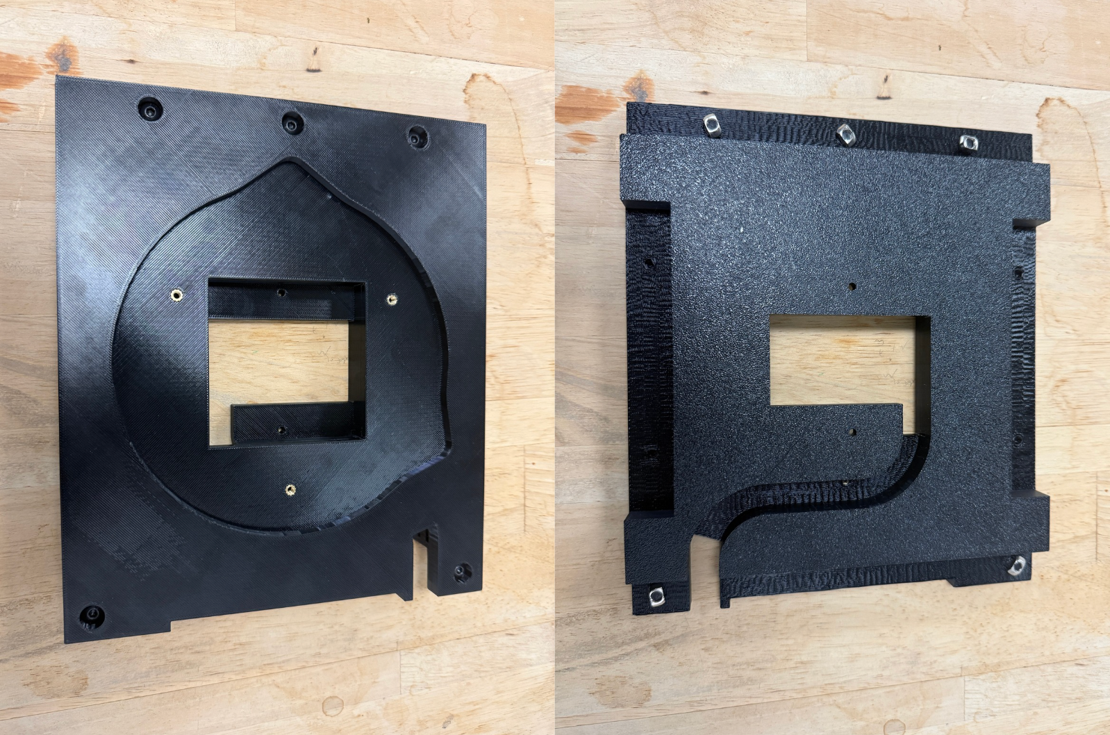
Remove the Bottom Plate of the rotation element from the assembly.
Solder wires from the LED to a 3 pin Dupont plug. Zip tie the wire in place to keep the Dupont connector exposed.
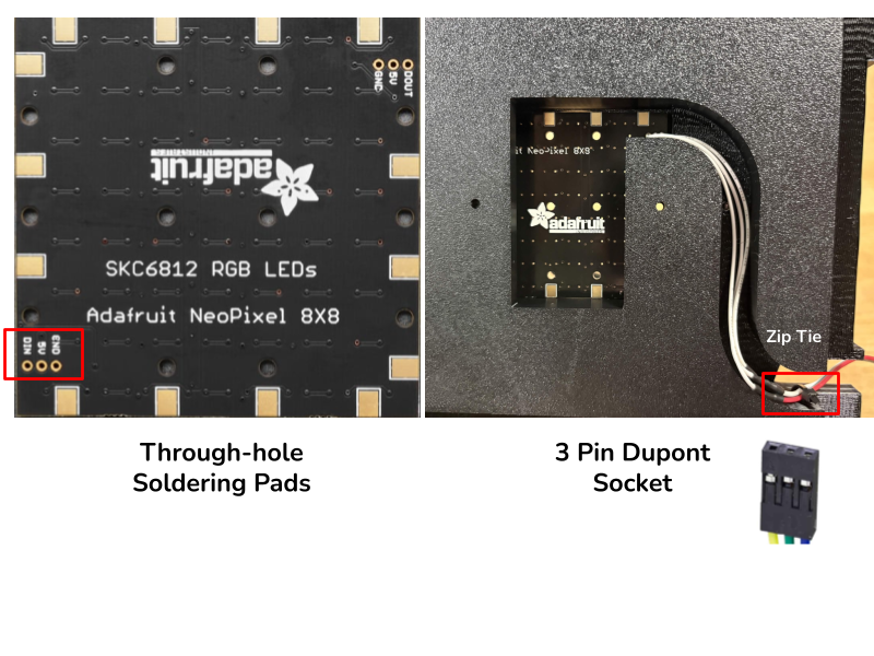
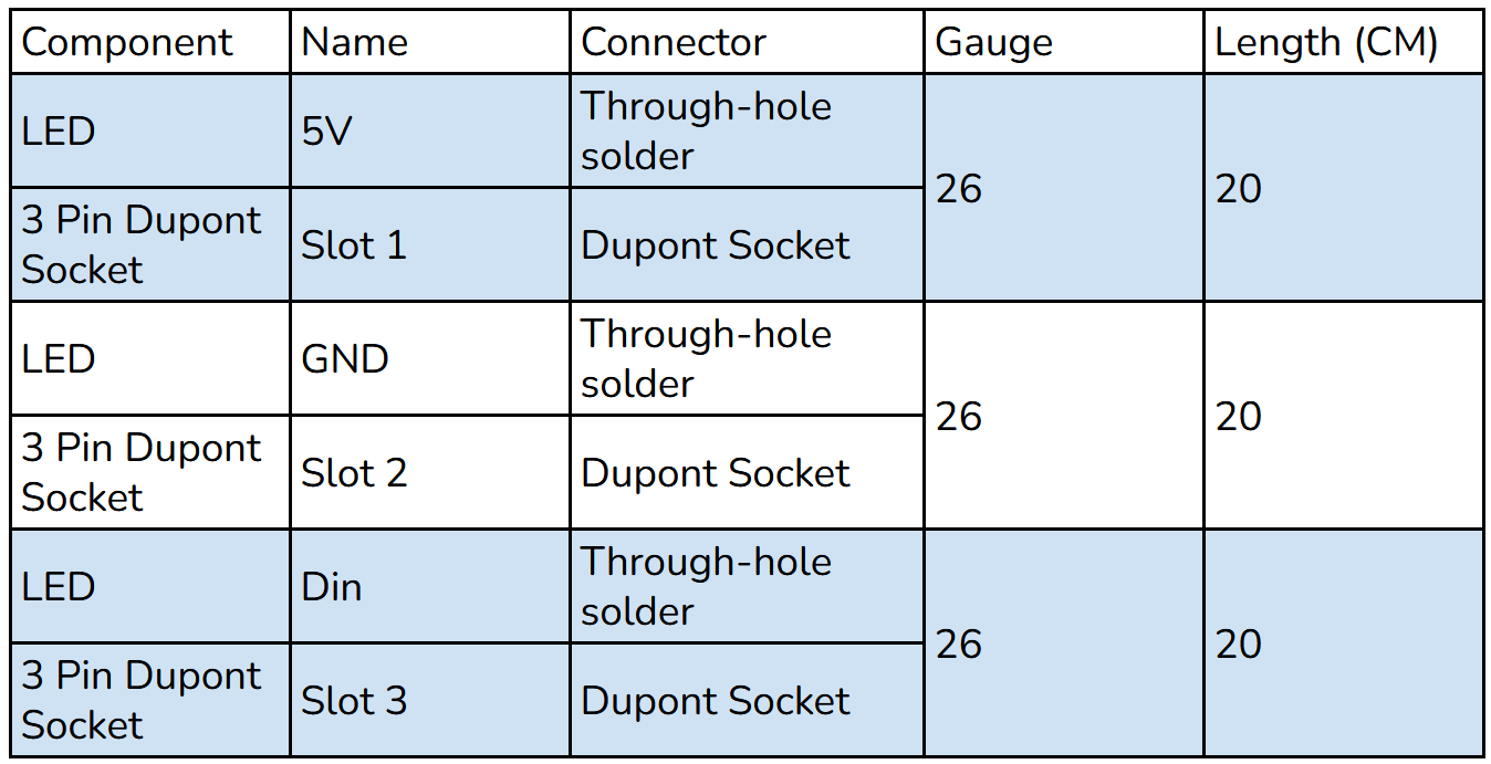
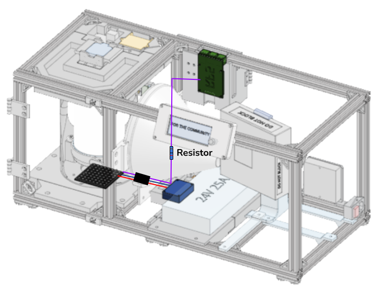
Connect a 3 pin Dupont receptacle to three wires, running power and ground to the Terminal Block and the data line to the RP5. Add a 300 Ohm resistor to the data line to prevent noise and power leeching. Reconnect the Bottom Plate to the assembly and plug the LED Dupont connectors.
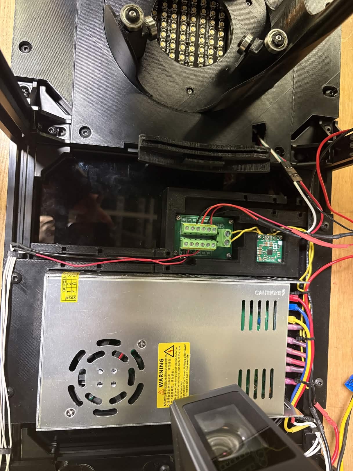
Camera
Note about camera assembly: if CSI to HDMI adapters are not available, a long CSI cable can be used as a substitute.
Remove the camera and CSI to HDMI adapter from the Camera Mount.
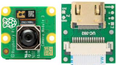
Run the CSI cable from the left side of the camera, behind the camera, and connect it to the adapter. This 22 pin to 22 pin CSI cable comes with the adapter set.
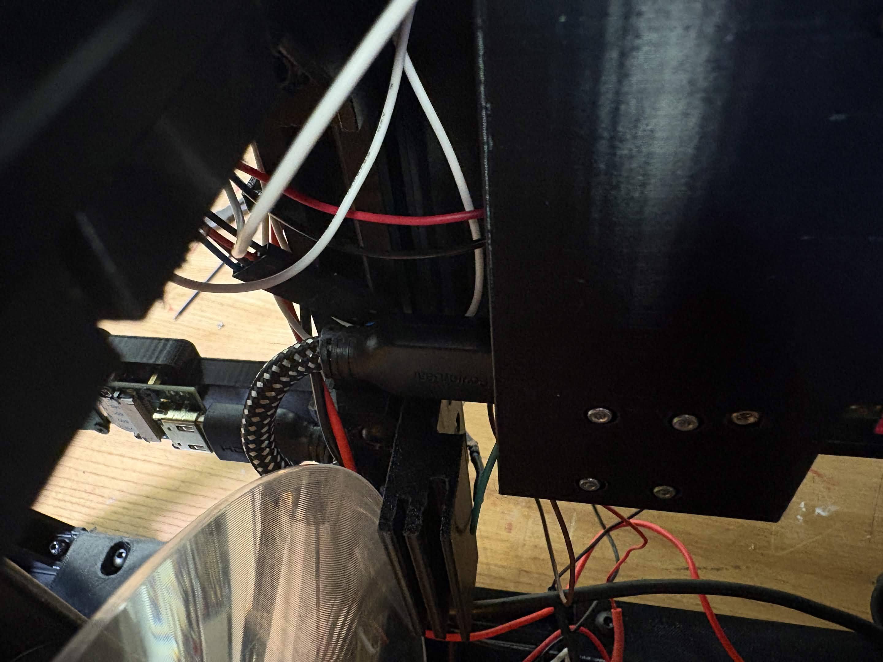
In the RP5 Housing assembly, connect the CSI to HDMI adapter to the RP5 using a CSI cable. This CSI cable is 22 pin to 15 pin.
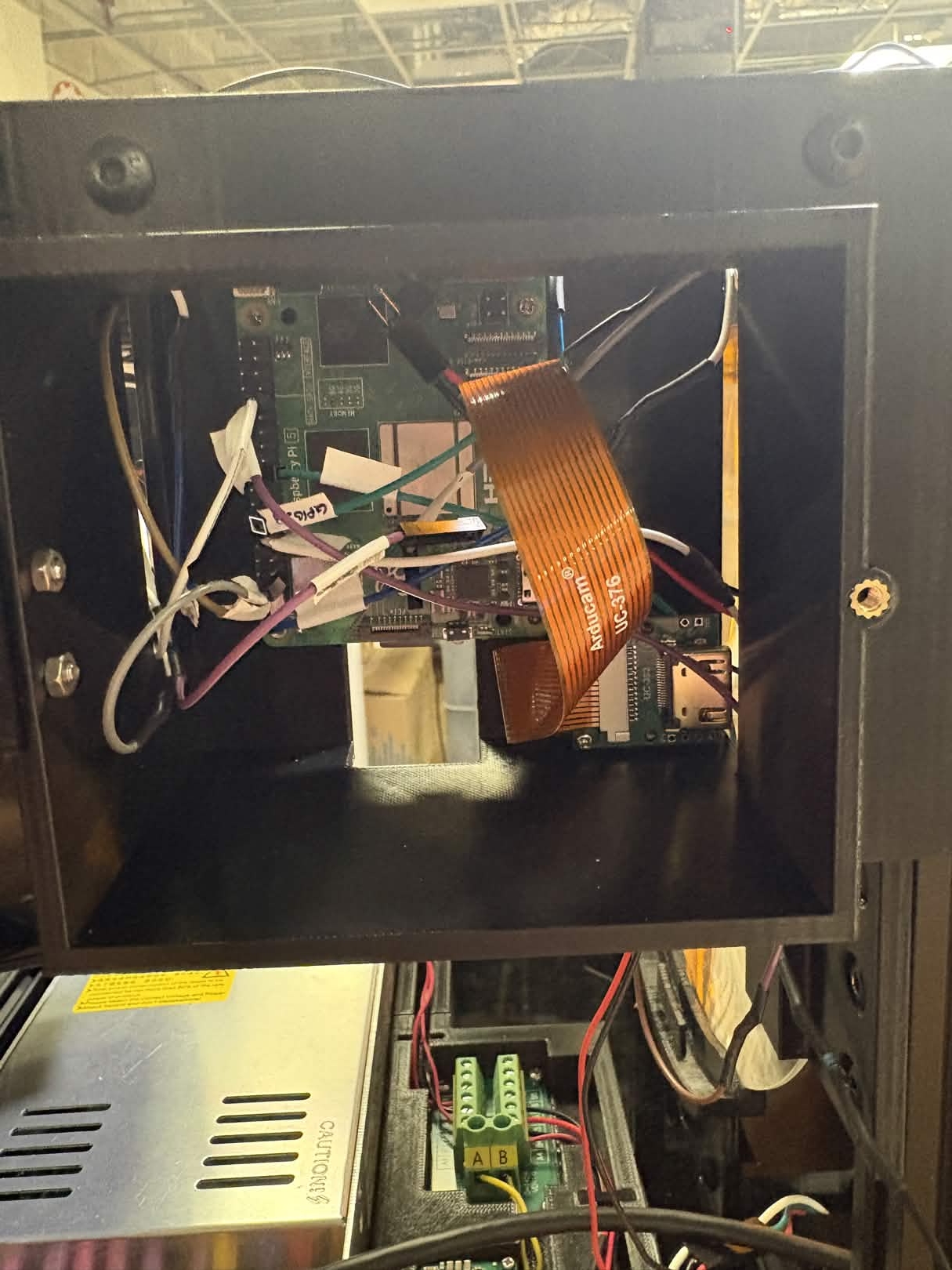
Connect the adapters using the 0.5 ft HDMI cable.
Remaining Connections
Connect the RP5 to 5V power by running a USB cable from the RP5 to the Terminal Block.
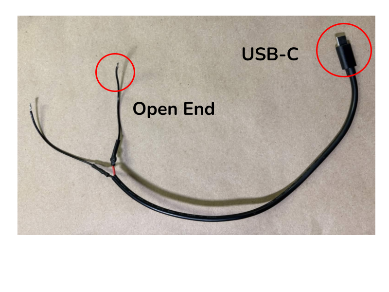
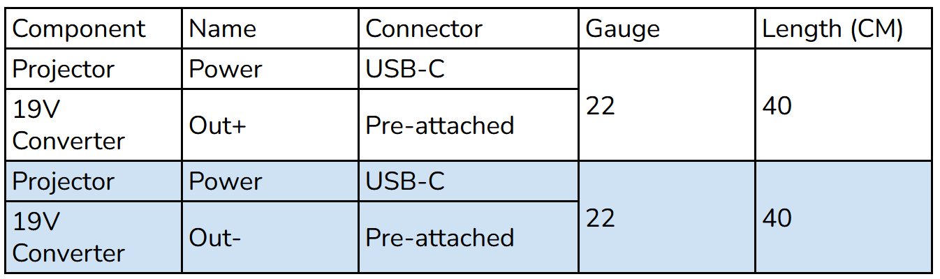
Connect the projector to 19V power by connecting wires from the 19V power output to the corresponding plug for projector power. For the NexiGo Nova Mini, this is a USB-C.
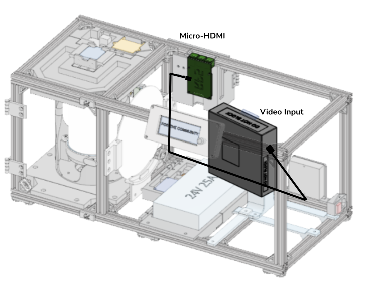
Connect the projector to the RP5 using a micro-HDMI to HDMI cable. If using an alternative projector with a different video input method, use a cable for connection from micro-HDMI to the corresponding input plug type.
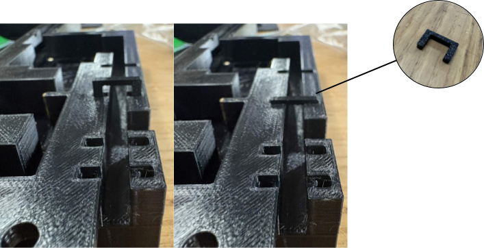
To secure wires on the Inner Housing Plate, use the press-fit clips along the wire routing cutouts.