Frame Subassemblies
The frame consists of the following subassemblies:
Aluminum Extrusion Frame
LCD Panel
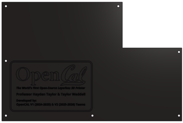
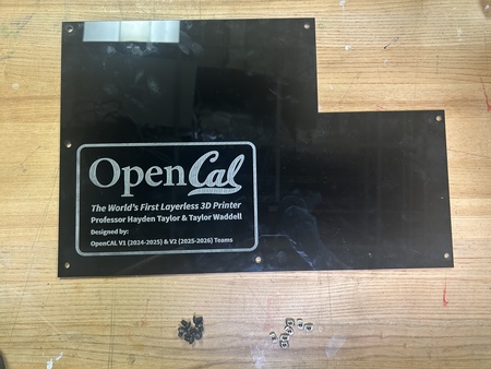
Back Projector Panel
Side Projector Panel
Top Projector Panel
Door
Top Vial Panel
Back Vial Panel
Side Vial Panel
Bottom Panels
Magnet Frame Inserts
NOTE: The Aluminum Extrusion Frame is the most critical subassembly. This is the very first thing that should be built for OpenCAL. The other subassemblies can be created and installed at any point.
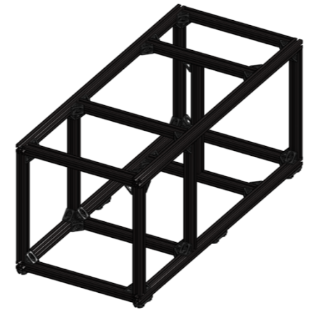
Aluminum Extrusion Frame
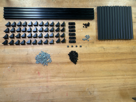
Required Materials:
(QTY 4) 65 cm Aluminum Extrusions
(QTY 13) 25 cm Aluminum Extrusions
(QTY 44) 90 deg Corner Gussets
(QTY 88) M5x8 Button Head Screws
(QTY 12) M5x10 Button Head Screws
(QTY 6) TPU Feet
(QTY 4) Magnet Frame Insert Assembly
(QTY 100) M5 TNut
Required Tools:
M3 Hex/Allen Key
Metric Measuring Tape
Step-by-Step Instructions:
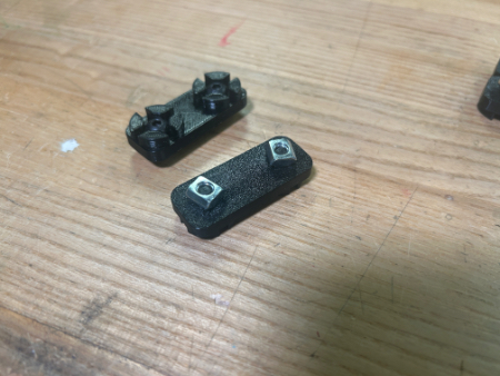
NOTE: All fasteners will be “hand tight”. ENSURE all TNuts are in the correct orientation (screw goes into flanged end). ENSURE all the sides of the 90 deg gussets are flush with their respective aluminum extrusions – this may need to be done after the rail positions are locked.
Layout all of the required materials and tools.
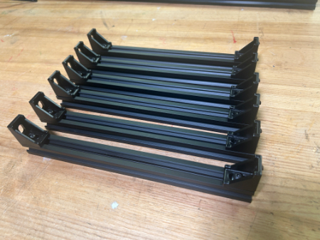
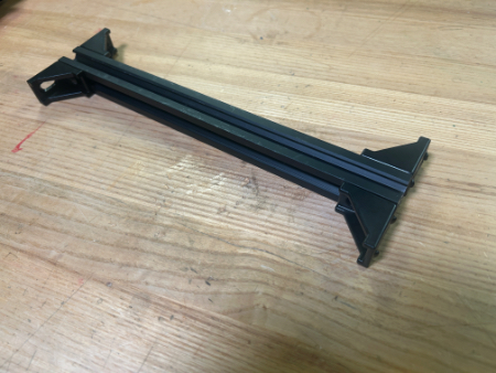
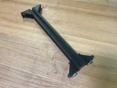
Attach QTY (4) 90 deg Corner Gussets to QTY (1) 25 cm Aluminum Extrusion using QTY (4) M5x8 Button Head Screws and QTY (4) M5 TNut in the following configuration:
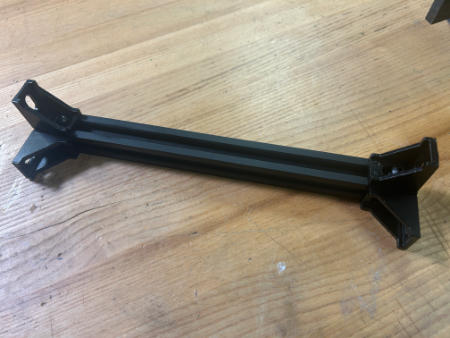
Install QTY (4) M5x8 Button Head Screws and QTY (4) M5 TNut into the other side of each of the QTY (4) 90 deg Corner Gussets.
Repeat Steps 2-3 three more times (should have a total of 4 of this assembly).
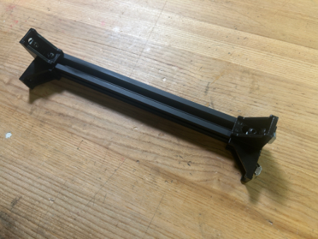
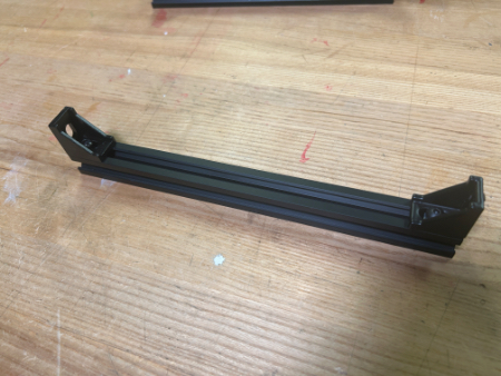
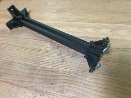
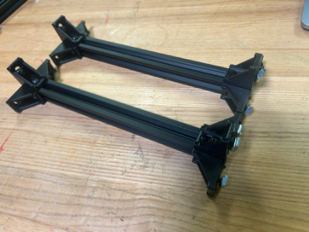
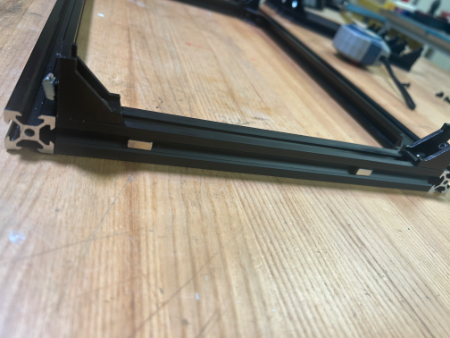
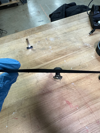
Attach QTY (2) 90 deg Corner Gussets to QTY (1) 25 cm Aluminum Extrusion using QTY (4) M5x8 Button Head Screws and QTY (4) M5 TNut in the following configuration. It is recommended to loosely install the screws and nuts on the gussets prior to rail installation (see image).
Repeat Step 5 five more times (should have a total of 6 of this assembly).
Attach QTY (6) 90 deg Corner Gussets to QTY (1) 25 cm Aluminum Extrusion using QTY (6) M5x8 Button Head Screws and QTY (6) M5 TNut in the following configuration:
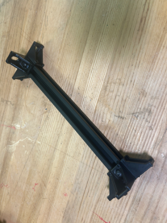
Install QTY (6) M5x8 Button Head Screws and QTY (6) M5 TNut into the other side of each of the QTY (6) 90 deg Corner Gussets.
Repeat Steps 7-8 one more time (should have a total of 2 of this assembly).
Attach QTY (4) 90 deg Corner Gussets to QTY (1) 25 cm Aluminum Extrusion using QTY (4) M5x8 Button Head Screws and QTY (4) M5 TNut in the following configuration:
Install QTY (4) M5x8 Button Head Screws and QTY (4) M5 TNut into the other side of each of the QTY (4) 90 deg Corner Gussets.
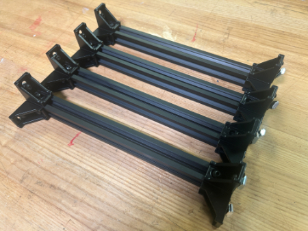
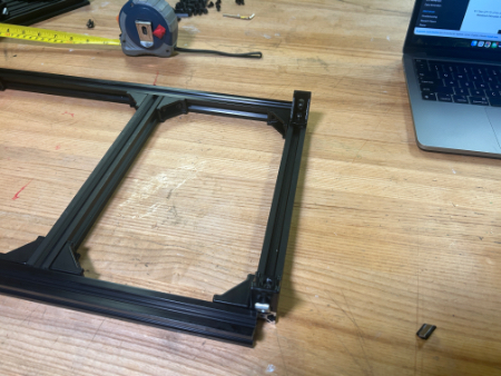
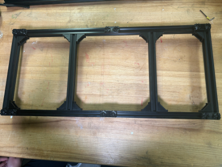
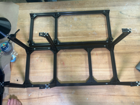
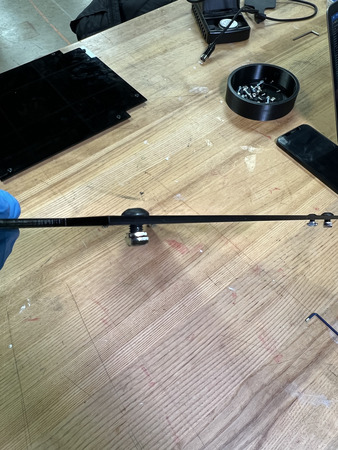
Take QTY (1) of the assemblies from Step 4 and slide it in between QTY (2) 65 cm Aluminum Extrusion to the very end in the following configuration. Tighten the QTY (2) M5x8 Button Head Screw that connects to the 65 cm rail.
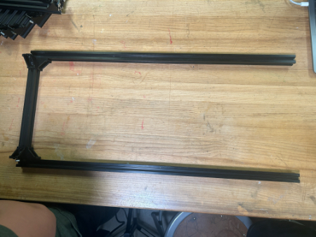
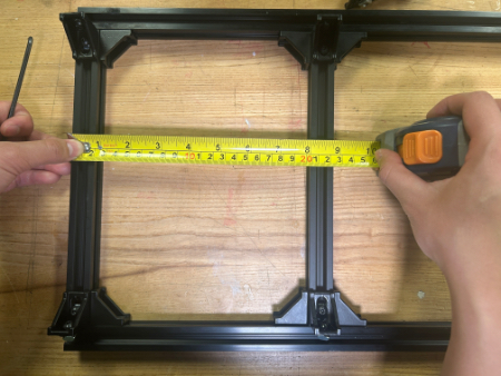
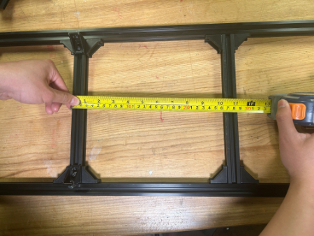
Take QTY (1) of the assemblies from Step 9 and slide it from the same point in between the QTY (2) 65 cm Aluminum Extrusion as Step 12 205mm from the end (front rail to front rail) in the following configuration:
Take QTY (1) of the assemblies from Step 10 and slide it from the same point in between the QTY (2) 65 cm Aluminum Extrusion in the following configuration. You may need to loosen the brackets from the previous two steps to slide it in. This rail location is temporary and will be changed in main assembly.
Take QTY (1) of the assemblies from Step 4, FLIP IT, and slide it in between QTY (2) 65 cm Aluminum Extrusion to the opposite end in the following configuration. Keep this loose for the next step.
Refer to the “Magnet Frame Insert” Subassembly to make QTY (2) Magnet Frame Insert.
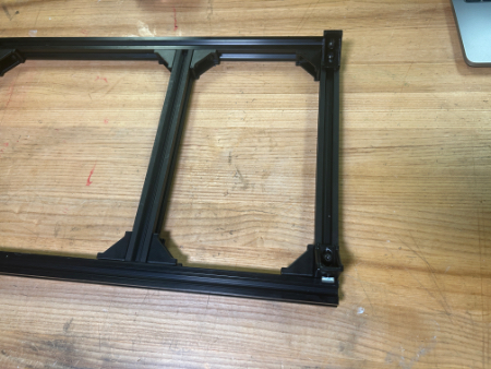
Pull out the rail from Step 15 so that the back railing is exposed, slide in QTY (2) Magnet Frame Insert. Slide the rail back to be flush with the end and tighten it.
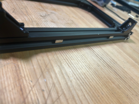
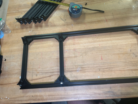
You should now have the bottom of the frame.
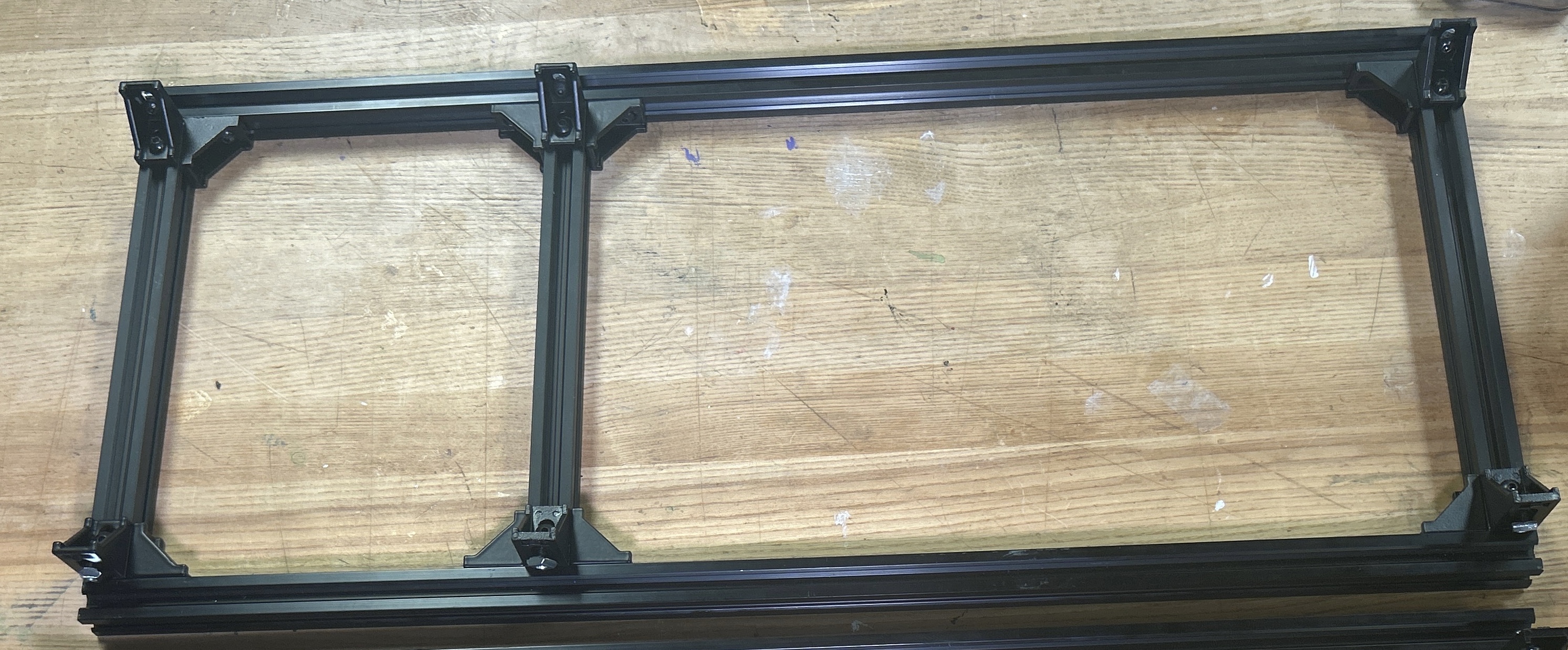
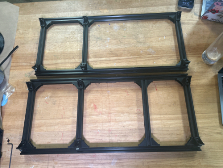
Repeat Steps 12, 13, 15, 16, & 17 with the remaining QTY (2) 65 cm Aluminum Extrusion. Note: The middle bar should be 205mm from the back.
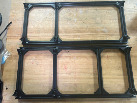
Take QTY (6) TPU Feet and install QTY (2) M5 TNut and QTY (2) M5x8 Button Head Screw into EACH foot (total 12 TNuts and screws should be used).
Take these assemblies and slide 3 of them on the bottom of each of the QTY (2) 65 cm Aluminum Extrusion from the bottom frame assembly. Two of the feet should go on each end and one should be near the center. Fasten these feet down.
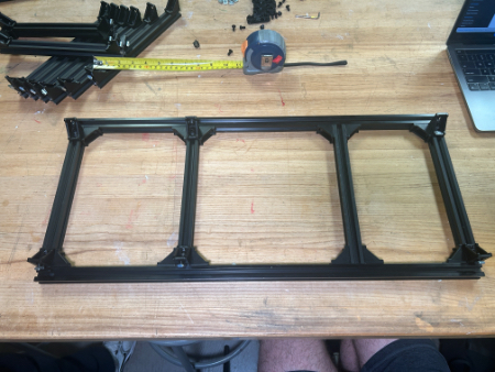
You should now have the top and bottom of the frame.
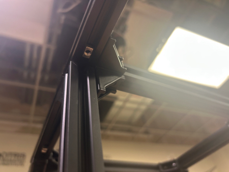
Slide in QTY (3) M5 TNut into the top of each of the QTY (4) 65 cm Aluminum Extrusion (a total of 12 M5 TNuts should be used). Position these near, but away from the vertical bracket locations (shown below).
Take QTY (6) of the assembly from Step 5 and, from the top down, vertically slide them into the Bottom Frame (top down) in the following configuration.
Slide the M5 TNuts from Step 23 under each of the QTY (6) 90 deg Corner Gussets and fasten down with QTY (6) M5x8 Button Head Screw. Also fasten the side fasteners that the vertical rail slides into. Loosen and tighten the brackets so that the vertical rails are flush (by touch) with the railings on each side.
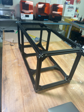
Carefully take the top assembly of the frame from Step 19 and, from the side (so that the M5 TNuts do not fall out), flip the assembly and align it with the vertical rails. Slowly slide in the top assembly, ensuring that the TNuts are going into all 6 of the vertical rails.
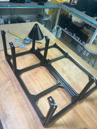
Slide the M5 TNuts from Step 23 under each of the QTY (6) 90 deg Corner Gussets and fasten down with QTY (6) M5x8 Button Head Screw. You will not be able to slide the M5 TNuts through the corner brackets due to the little locater knobs on them. You may need to loosen the corner brackets, bring it down, align the TNut, and bring it back up and tighten.
Ensure all railing and 90 deg corner brackets are flush with each other. Ensure all fasteners are completely hand tight. The Aluminum Extrusion Frame is now complete.
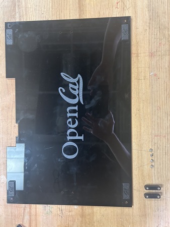
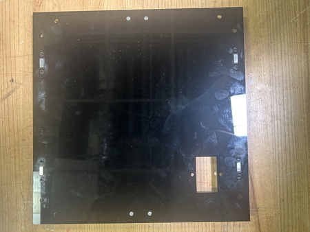
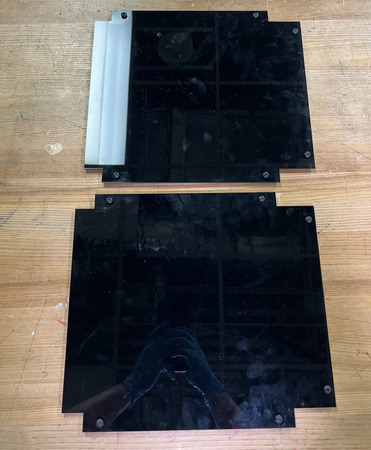
LCD Panel

Required Materials:
NOTE: The Magnet Holders have been already glued in & the Heat Inserts have already been installed.
(QTY 1) LCD Panel
(QTY 8) 12x5x2mm Rare Earth Magnet Bars
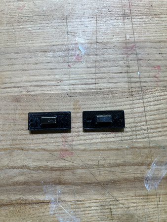
(QTY 4) Magnet Holder
(QTY 2) Panel Handle
(QTY 4) M3x4x5 Heat Set Insert
(QTY 4) M3x6 Button Head Screw
Required Tools:
Soldering Iron
M2 Hex/Allen Key
Super Glue
Step-by-Step Instructions:
NOTE 1: Ensure all magnets are the correct polarity. Do this by keeping the magnets together and only taking a magnet out one by one and placing them in the same orientation (same side down). If the polarities get flipped, you may need to repeat some steps.
NOTE 2: The Magnet Holders had already been glued on to the panel prior to instruction writing. Images will reflect this.
Lay a QTY (1) Magnet Holders on the flat end. Add a drop of super glue into the center box. Carefully place QTY (1) 12x5x2mm Rare Earth Magnet Bar in the center box. Wait ~ 2 minutes for cure.
After cure, place another drop of super glue on top of the magnet from Step 1. Carefully place another QTY (1) 12x5x2mm Rare Earth Magnet Bar in the same orientation on top of the previous magnet (ensure that the magnets are in the same polar orientation and are aligned with each other).
Repeat Steps 1 & 2 three more times. You should have 4 of these assemblies total.
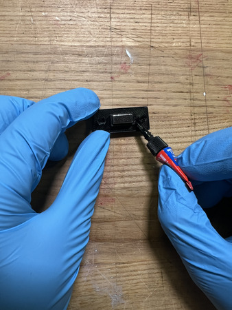
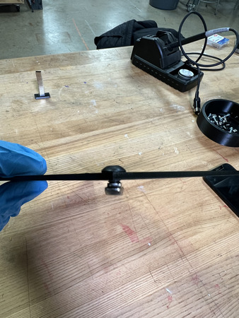
Insert QTY (2) M3x4x5 Heat Set Insert into each of the holes on the back of QTY (1) Panel Handle using a soldering iron. To the best of your ability, ensure the heat inserts are straight.
Repeat Step 4 one more time. You should have 2 handles with installed inserts.
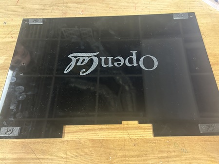
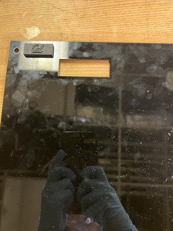
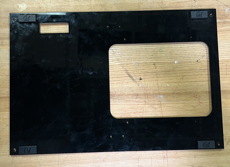
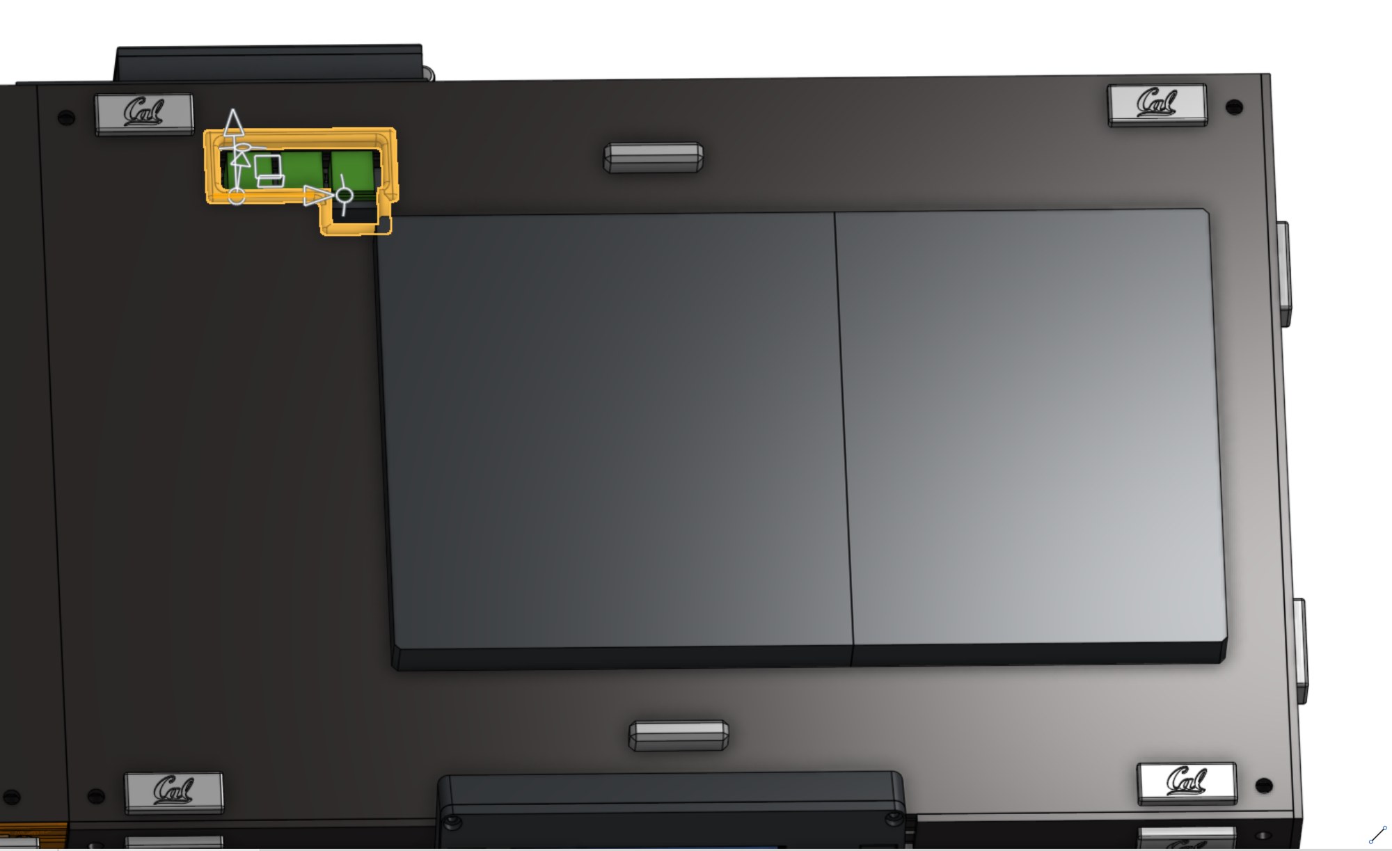
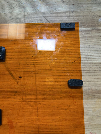
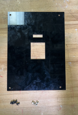
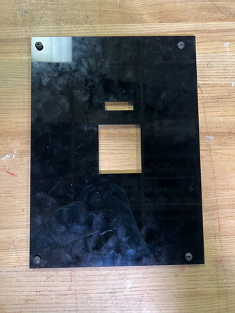
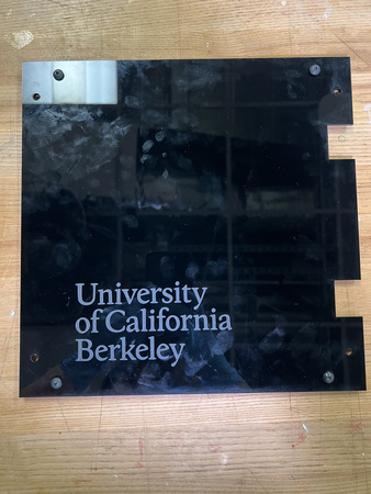
Add a couple dabs of super glue around the panel interface of the magnet holders (seen below). Press it into the top left of the QTY (1) LCD panel (from the front of the panel – the part with the logo) at the designated location. Add more pressure to ensure a flush fit.
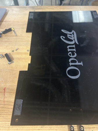
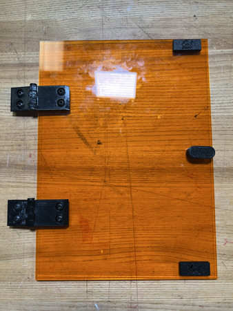
Repeat Step 6 three more times with the remaining assemblies from Step 3 at each of the corners of the panel. Ensure all magnets are facing the correct way (right-side up CAL logo).
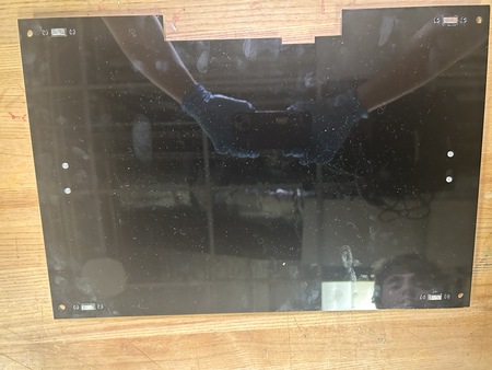
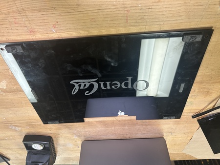
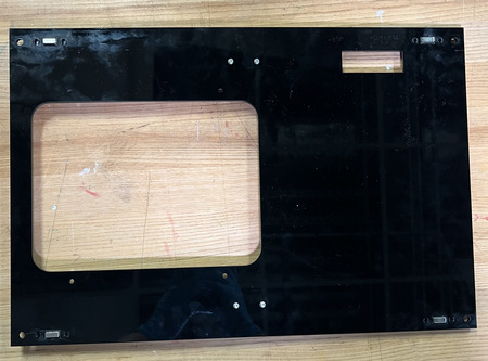
Install the QTY (2) Panel Handle Assemblies from Step 5 by screwing them in with QTY (4) M3x6 Button Head Screws in the following locations.
The LCD Panel subassembly is now complete.
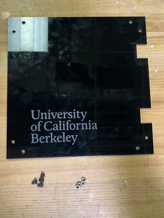
Back Projector Panel
Required Materials:
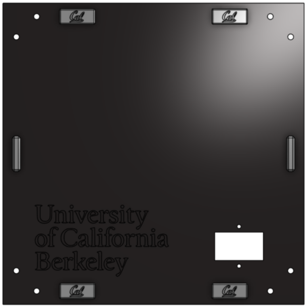
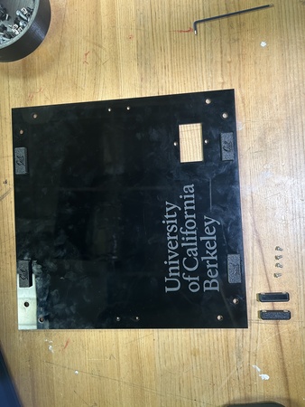
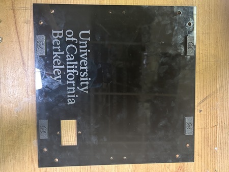
(QTY 1) Back Projector Panel
(QTY 7) M5x8 Button Head Screws
(QTY 7) M5 Hammer TNut
Required Tools:
No Tools Required.
Step-by-Step Instructions:
NOTE 1: Ensure all Hammer TNuts are in the correct orientation (wide end on bottom).
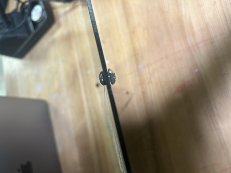
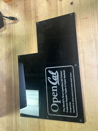
Place QTY (7) M5x8 Button Head Screw through each of the holes on the QTY (1) Back Projector Panel from the front (face with logo). Loosely install QTY (7) M5 Hammer TNut on the opposite ends.
The Back Projector Panel subassembly is now complete.
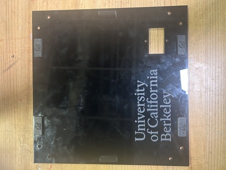
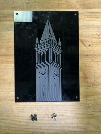
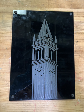
Side Projector Panel
Required Materials:
(QTY 1) Side Projector Panel
(QTY 8) 12x5x2mm Rare Earth Magnet Bars
(QTY 4) Magnet Holder
(QTY 2) Panel Handle
(QTY 4) M3x4x5 Heat Set Insert
(QTY 4) M3x6 Button Head Screw
Required Tools:
Soldering Iron
M2 Hex Key
Super Glue
Step-by-Step Instructions:
NOTE 1: Ensure all magnets are the correct polarity. Do this by keeping the magnets together and only taking a magnet out one by one and placing them in the same orientation (same side down). If the polarities get flipped, you may need to repeat some steps.
NOTE 2: The Magnet Holders had already been glued on to the panel prior to instruction writing. Images will reflect this.
Lay a QTY (1) Magnet Holder on the flat end. Add a drop of super glue into the center box. Carefully place QTY (1) 12x5x2mm Rare Earth Magnet Bar in the center box. Wait ~ 2 minutes for cure.
After cure, place another drop of super glue on top of the magnet from Step 1. Carefully place another QTY (1) 12x5x2mm Rare Earth Magnet Bar in the same orientation on top of the previous magnet (ensure that the magnets are in the same polar orientation and are aligned with each other).
Repeat Steps 1 & 2 three more times. You should have 4 of these assemblies total.
Insert QTY (2) M3x4x5 Heat Set Insert into each of the holes on the back of QTY (1) Panel Handle using a soldering iron. To the best of your ability, ensure the heat inserts are straight.
Repeat Step 4 one more time. You should have 2 handles with installed inserts.
Add a couple dabs of super glue around the panel interface of the magnet holders (seen below). Press it into the top left of the QTY (1) Side Projector Panel (from the front of the panel) at the designated location. Add more pressure to ensure a flush fit.
Repeat Step 6 three more times with the remaining assemblies from Step 3 at each of the corners of the panel. Ensure all magnets are facing the correct way (right-side up CAL logo).
Install the QTY (2) Panel Handle Assemblies from Step 5 by screwing them in with QTY (4) M3x6 Button Head Screws in the following locations.
(Not shown in images). Loosely install QTY (4) M5x8 Button Head Screw and QTY (4) M5 Hammer TNut on each corner of the panel. Do not tighten these down as this will occur during Main Assembly Part 2.
The Side Projector Panel subassembly is now complete.
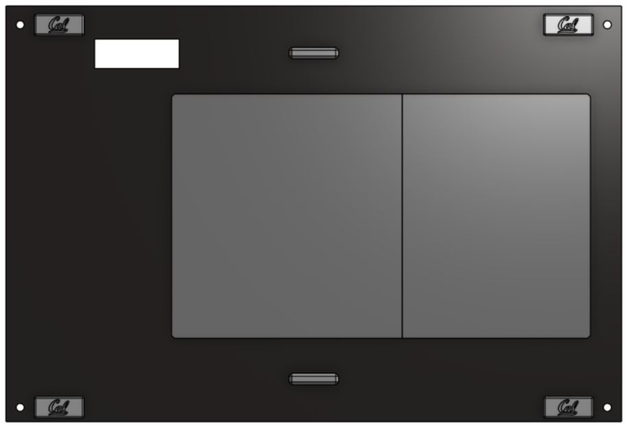
Top Projector Panel
Required Materials:
NOTE: Heat set inserts have already been installed into Top Caps. Rare Earth Magnet Bars have already been installed into magnet holders and panel. RP5 Guard is not depicted.
(QTY 1) Top Projector Panel
(QTY 1) Top Cap 1
(QTY 1) Top Cap 2
(QTY 8) 12x5x2mm Rare Earth Magnet Bars
(QTY 4) Magnet Holder
(QTY 2) Panel Handle
(QTY 4) M3x4x5 Heat Set Insert
(QTY 10) M3x6x5 Heat Set Insert
(QTY 4) M3x6 Button Head Screw
(QTY 8) M3x8 Button Head Screw
(QTY 1) RP5 Guard
Required Tools:
Soldering Iron
M2 Hex Key
Super Glue
Step-by-Step Instructions:
NOTE: Ensure all magnets are the correct polarity. Do this by keeping the magnets together and only taking a magnet out one by one and placing them in the same orientation (same side down). If the polarities get flipped, you may need to repeat some steps.
Lay a QTY (1) Magnet Holders on the flat end. Add a drop of super glue into the center box. Carefully place QTY (1) 12x5x2mm Rare Earth Magnet Bar in the center box. Wait ~ 2 minutes for cure.
After cure, place another drop of super glue on top of the magnet from Step 1. Carefully place another QTY (1) 12x5x2mm Rare Earth Magnet Bar in the same orientation on top of the previous magnet (ensure that the magnets are in the same polar orientation and are aligned with each other).
Repeat Steps 1 & 2 three more times. You should have 4 of these assemblies total.
Insert QTY (2) M3x4x5 Heat Set Insert into each of the holes on the back of QTY (1) Panel Handle using a soldering iron. To the best of your ability, ensure the heat inserts are straight.
Repeat Step 4 one more time. You should have 2 handles with installed inserts.
Add a couple dabs of super glue around the panel interface of the magnet holders (seen below). Press it into the top left of the QTY (1) Top Projector Panel (from the front of the panel– small hole is on the left, big hole is on the right) at the designated location. Add more pressure to ensure a flush fit.
Repeat Step 6 three more times with the remaining assemblies from Step 3 at each of the corners of the panel. Ensure all magnets are facing the correct way (right-side up CAL logo).
Install the QTY (2) Panel Handle Assemblies from Step 5 by screwing them in with QTY (4) M3x6 Button Head Screws in the following locations.
Install the QTY (1) Top Cap 1 and QTY (1) Top Cap 2 to the same side as the handles (top side) using QTY (10) M3x8 Button Head Screw from the opposite end of the panel. The Top Caps, when placed together, are symmetrical so it does not matter what orientation, see image below.
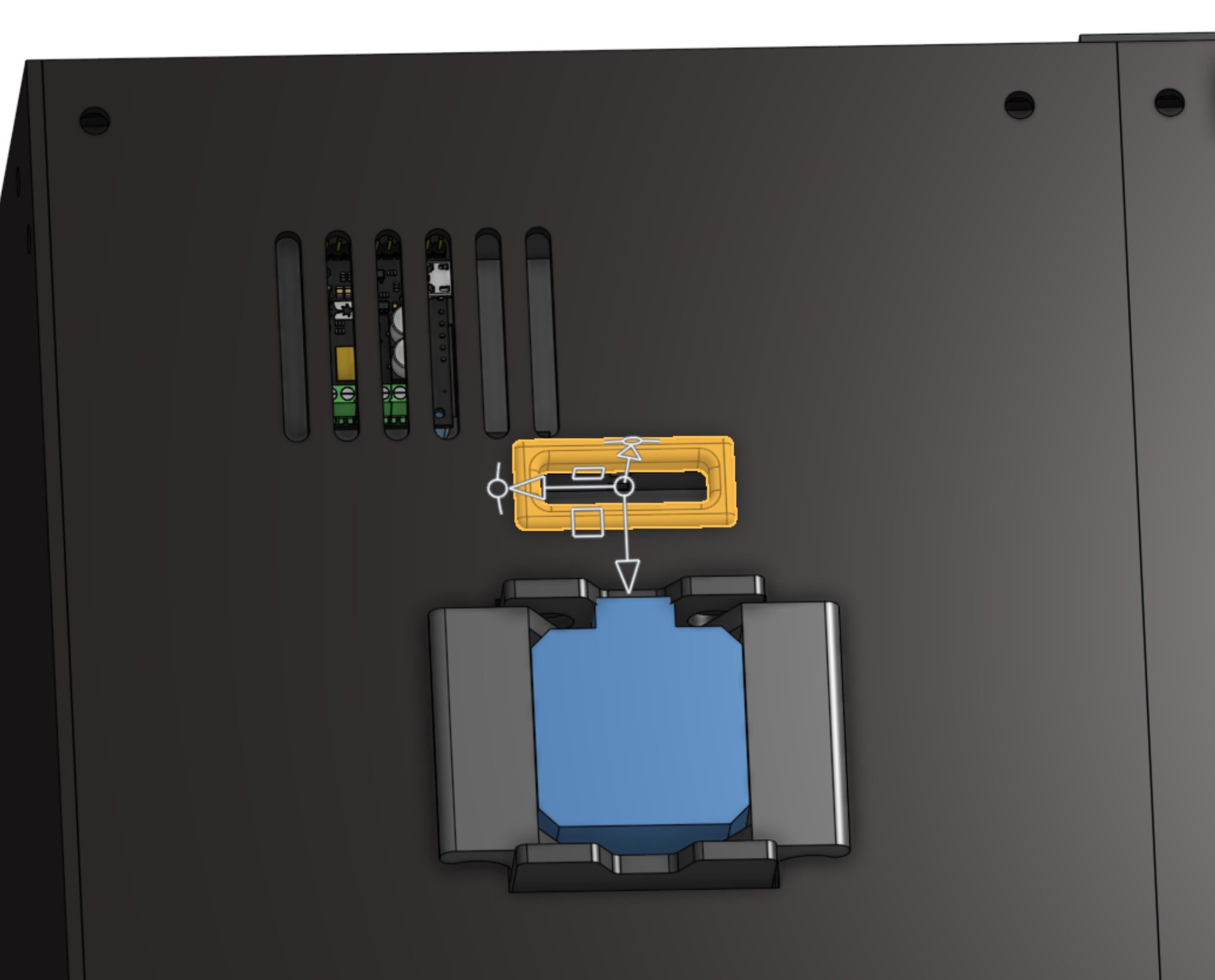
Glue on QTY (1) RP5 Guard in the small hole on the Top Projector Panel.
NOTE: The Raspberry Pi guard and its hole were updated to accommodate the USB mount for the motor controller.
The Top Projector Panel subassembly is now complete.
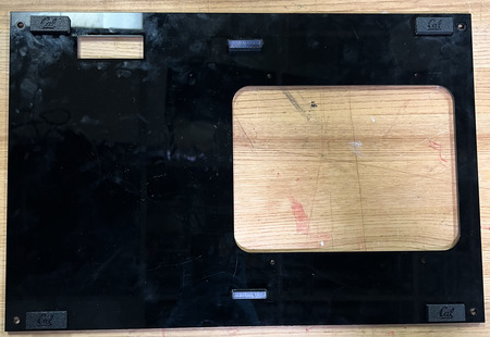
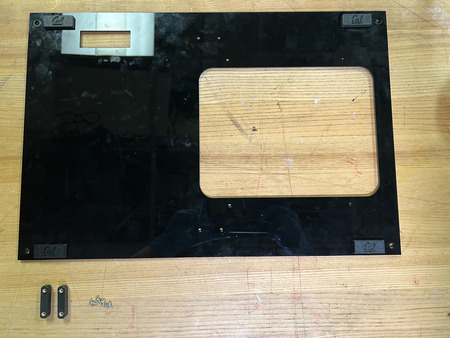
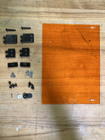
Door
Required Materials:
NOTE: Heat Set Insert has already been installed into the Door Handle.
(QTY 1) Door Panel
(QTY 2) Magnet Holder
(QTY 4) 12x5x2mm Rare Earth Magnet Bars
(QTY 1) M3x6x5 Heat Set Insert
(QTY 1) M3x8 Button Head Screw
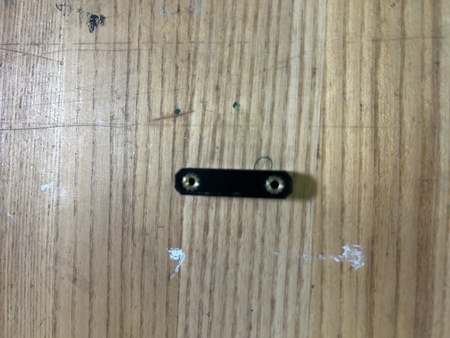
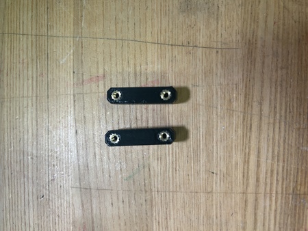
(QTY 2) Short Hinge
(QTY 2) Long Hinge
(QTY 2) Hinge Pin
(QTY 4) M5x8 Button Head Screw
(QTY 4) M5x10 Button Head Screw
(QTY 4) M5 Hex Nut/M5 TNut
(QTY 4) M5 Hammer TNut
(QTY 1) Door Handle
(QTY 1) M3 Washer
Required Tools:
Soldering Iron
M3 Allen Wrench
M2 Allen Wrench
Super Glue
Step-by-Step Instructions:
NOTE: The Heat Set Insert and Magnets have already been installed to the Door Handle and Magnet Holders Respectively. Images will reflect this.
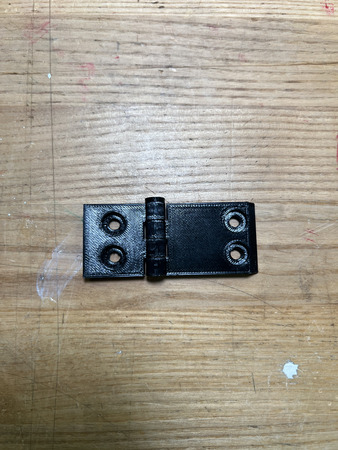
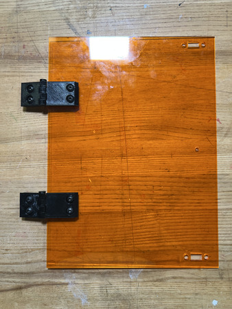
Align QTY (1) Short Hinge with QTY (1) Long Hinge with the short hinge on the left and long hinge on the right. Ensure it is in the following orientation:
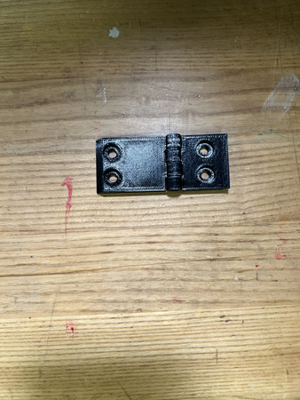
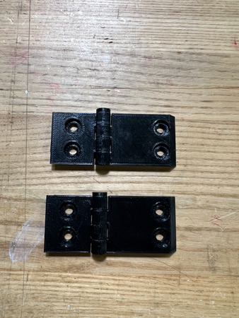
Insert QTY (1) Hinge Pin from the top, ensuring that it goes all the way through.
Repeat Steps 1 & 2 one more time. You should have 2 of these assemblies.
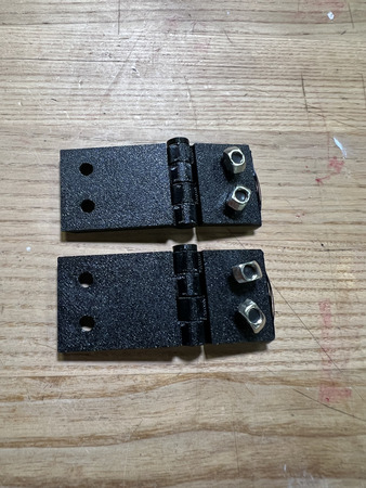
On the QTY (2) Short Hinge, loose install QTY (4) M5x8 Button Head Screw with QTY (4) M5 Hammer TNut.
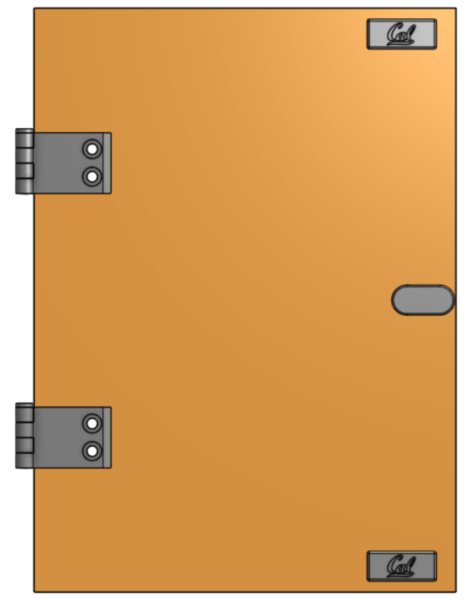
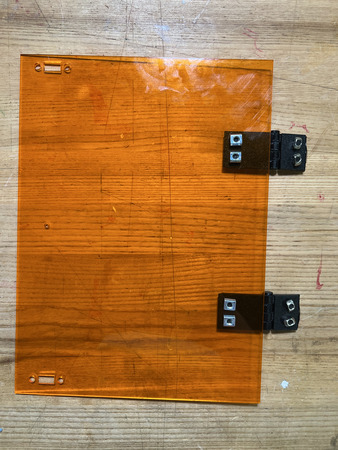
Align the holes of the QTY (2) Long Hinge part of the assembly with the corresponding holes in the FRONT of the QTY (1) Door panel. Install using QTY (4) M5x10 Button Head Screw and QTY (4) M5 Hex Nut/TNut. The front of the panel is designated as the side with the hinge holes on the left and handle hole on the right. Ensure that the hinge pin is on the top of the hinge assembly and not the bottom.
Install QTY (1) M3x4x5 Heat Set Insert into the QTY (1) Door Handle from the back.
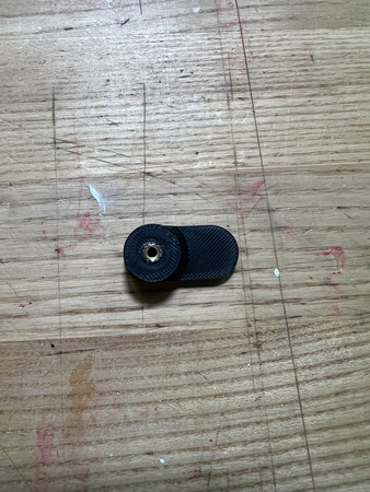
Install the assembly from Step 6 with QTY (1) M3x8 Button Head Screw and QTY (1) M3 Washer from the back. The handle should be on the right side.
Lay a QTY (1) Magnet Holders on the flat end. Add a drop of super glue into the center box. Carefully place QTY (1) 12x5x2mm Rare Earth Magnet Bar in the center box. Wait ~ 2 minutes for cure.
After cure, place another drop of super glue on top of the magnet from Step 1. Carefully place another QTY (1) 12x5x2mm Rare Earth Magnet Bar in the same orientation on top of the previous magnet (ensure that the magnets are in the same polar orientation and are aligned with each other).
Repeat Steps 8 & 9 one more time. You should have 2 of these assemblies total.
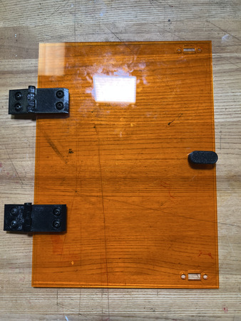
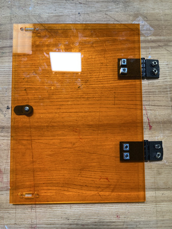
Add a couple dabs of super glue around the panel interface of the magnet holders (seen below). Press it into the top right of the QTY (1) Door Panel (from the front of the panel) at the designated location. Add more pressure to ensure a flush fit.
Repeat Step 11 one more time with the remaining assembly from Step 10 at the bottom right corner of the panel. Ensure all magnets are facing the correct way (right-side up CAL logo).
The Door Subassembly is now complete.
Top Vial Panel

NOTE: This panel now includes a vent (the slots next to the wire-guard slot) for better airflow over the motor controller.
Required Materials:
(QTY 1) Top Vial Panel
(QTY 4) M5x8 Button Head Screws
(QTY 4) M5 Hammer TNut
(QTY 1) Motor Wire Guard
Required Tools:
(QTY 1) Super Glue
Step-by-Step Instructions:
NOTE 1: Ensure all Hammer TNuts are in the correct orientation (wide end on bottom).
Place QTY (4) M5x8 Button Head Screw through each of the holes on the QTY (1) Top Vial Panel from the front (this is NOT symmetrical–the front is when the small hole is on top of the big hole and the wider side (relative to center hole) is on the left and narrower side is on the right). Loosely install QTY (4) M5 Hammer TNut on the opposite ends.
Glue on QTY (1) Motor Wire Guard in the small hole on the Top Vial Panel.
The Top Vial Panel subassembly is now complete.
Back Vial Panel

Required Materials:
(QTY 1) Back Vial Panel
(QTY 4) M5x8 Button Head Screws
(QTY 4) M5 Hammer TNut
Required Tools:
No Tools Required.
Step-by-Step Instructions:
NOTE 1: Ensure all Hammer TNuts are in the correct orientation (wide end on bottom).
Place QTY (4) M5x8 Button Head Screw through each of the holes on the QTY (1) Back Vial Panel from the front (face with logo). Loosely install QTY (4) M5 Hammer TNut on the opposite ends.
The Back Vial Panel subassembly is now complete.
Side Vial Panel

Required Materials:
(QTY 1) Side Vial Panel
(QTY 4) M5x8 Button Head Screws
(QTY 4) M5 Hammer TNut
Required Tools:
No Tools Required.
Step-by-Step Instructions:
NOTE 1: Ensure all Hammer TNuts are in the correct orientation (wide end on bottom).
Place QTY (4) M5x8 Button Head Screw through each of the top and bottom corner holes on the QTY (1) Side Vial Panel from the front (face with logo). Loosely install QTY (4) M5 Hammer TNut on the opposite ends.
The Side Vial Panel subassembly is now complete.
Bottom Panels


Required Materials:
(QTY 2) Bottom Panel
(QTY 12) M5x8 Button Head Screws
(QTY 12) M5 Hammer TNut
Required Tools:
No Tools Required.
Step-by-Step Instructions:
NOTE 1: Ensure all Hammer TNuts are in the correct orientation (wide end on bottom).
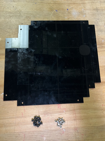
Place QTY (6) M5x8 Button Head Screw through each of the holes on the QTY (1) Bottom Panel from the front (choose one side, panel is symmetrical). Loosely install QTY (6) M5 Hammer TNut on the opposite ends.
Repeat Step 1 one more time. The Bottom Panels subassembly is now complete.
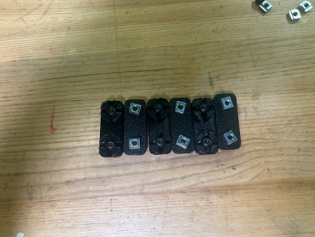
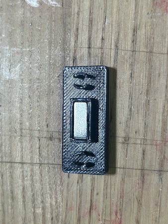
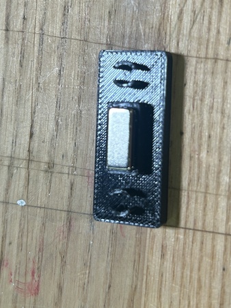
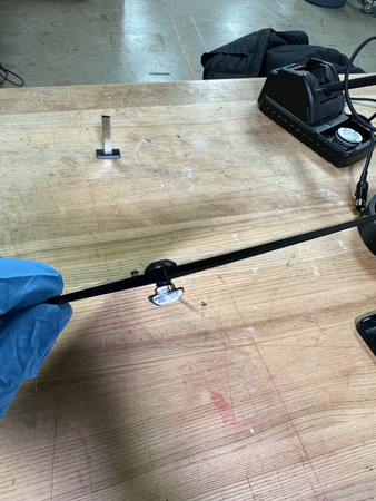
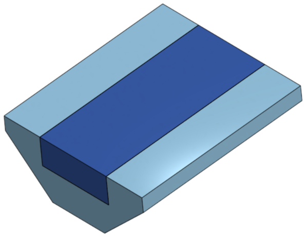
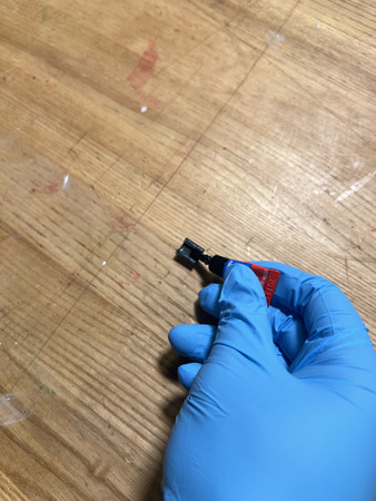
Magnet Frame Inserts
Required Materials:
(QTY 10) Magnet Frame Insert
(QTY 10) 12x5x2mm Rare Earth Magnet Bar
Required Tools:
Super Glue
Step-by-Step Instructions:
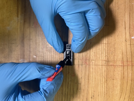
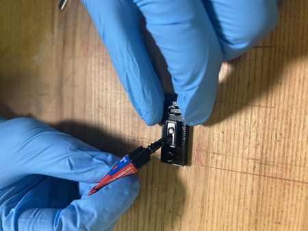
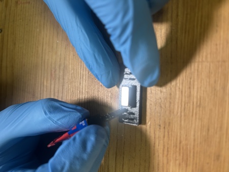
NOTE: Wear gloves while doing this so super glue does not contact your skin. Also, ENSURE the magnets are all in the same polarity as the panels
NOTE: These Magnet Frame Inserts will be installed after the printer is completed so that they do not fall out and get lost.
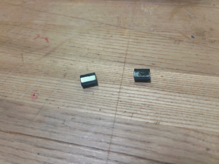
Place a dab of super glue into the crevice of QTY (1) Magnet Frame Insert. Place QTY (1) 12x5x2mm Rare Earth Magnet Bar on top of the crevice to bond the magnet.
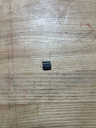
Repeat Step 1 nine more times. You should have 10 of these assemblies total.
The Magnet Frame Insert Subassembly is now complete.