Main Assembly
NOTE: ALL SUBASSEMBLIES MUST BE COMPLETED PRIOR TO BEGINNING THIS PROCESS
NOTE: WIRING WILL TAKE PLACE AFTER THIS IS COMPLETED.
Components List
Frame Subassemblies:
Aluminum Extrusion Frame
LCD Panel
Back Projector Panel
Side Projector Panel
Top Projector Panel
Door
Top Vial Panel
Back Vial Panel
Side Vial Panel
Bottom Panels
Magnet Frame Inserts
Optics Subassemblies:
Collimating Lens Mounts
Projector Mount
Rotational Element Subassemblies:
Rotation Stage
Large Vial
Small Vial
Front & Back Base Plates
Front Top Plate
Back Top Plate
Stepper Motor
Electronics Subassemblies:
Bottom Plate
Top Plate
LCD Housing
19V Converter Assembly
Raspberry Pi Housing
Camera Mount
Non-Subassemblies:
(QTY 1) Projector Shroud
(QTY 1) X Locator
(QTY 1) 200mm Fresnel Lens
Main Assembly Process - Part 1
Required Tools:
M3 Hex/Allen Key
Metric Measuring Tape
Digital/Metric Calipers
Step-by-Step Instructions
NOTE 1: All fasteners will be “hand tight”. Ensure all TNuts are in the correct orientation (screw goes into flanged end). Ensure all Hammer TNuts are in the rail before tightening.
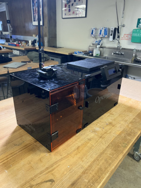
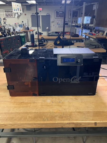
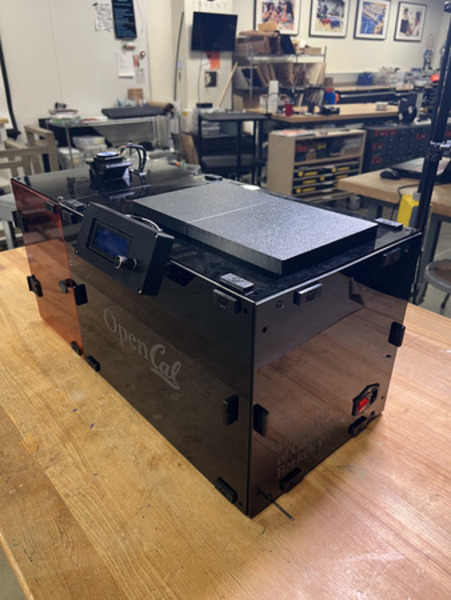
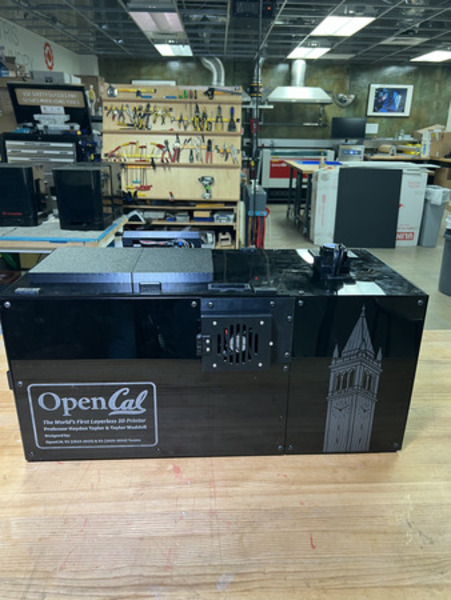
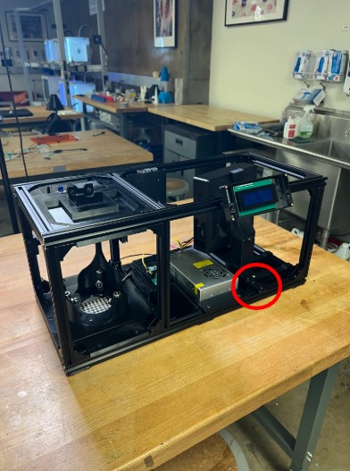
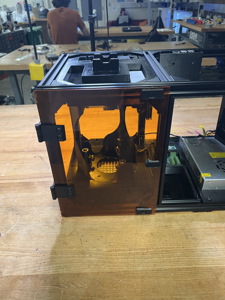
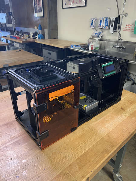
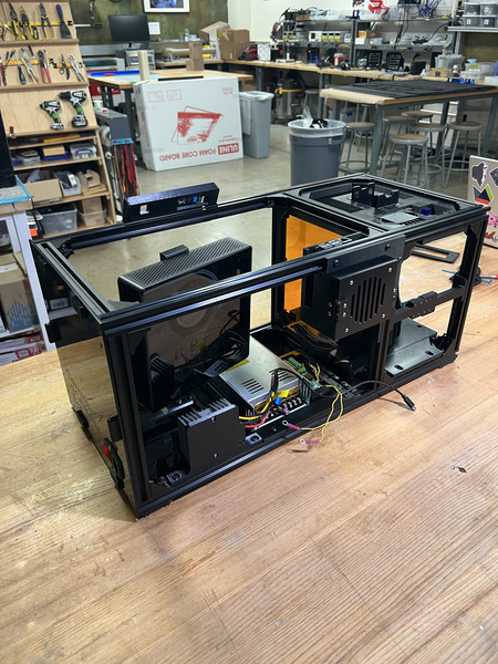
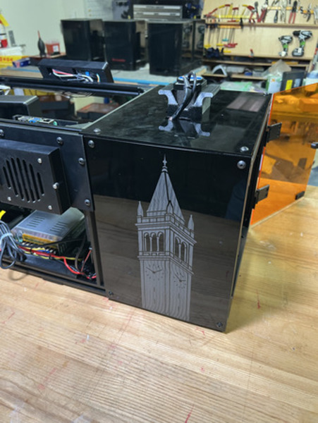
NOTE 2: The “front” of the printer is the face where the vial section (smaller section) is on the left and optics section is on the right.
NOTE 3: Positioning will not be referred to in text. See images for positioning.
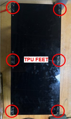
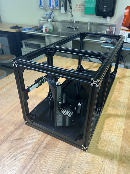
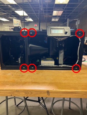
Flip the frame so that it is laying on the top. Loosen the TPU feet. Install the two Bottom Panels from the Frames Subassemblies. Each of the bottom panels have cutouts in each corner, with one cutout being larger than the other. The larger cutout should be on the end corners of the frame and small cutouts should be towards the center. You may need to move the feet to fit in these cutouts. Align all of the nuts with their respective railings, place down, and tighten the M5 fasteners. Also tighten the TPU Feet. If the bottom panels do not fit together/are not flush with the bottom of the frame, it is because it is not flush on the ends or the TPU feet need to be moved (there might be a slight gap in between the panels but that is fine).
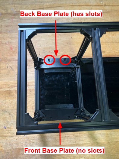
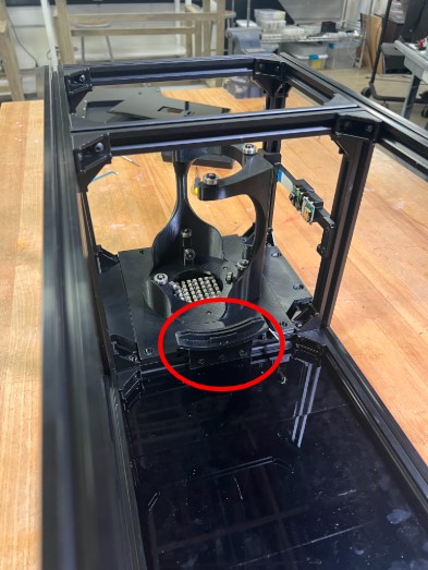
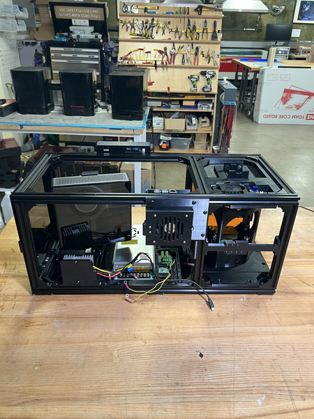
Flip the frame so that it is sitting on the TPU feet. Install the Front Base Plate in the position below. Tighten the M5 fasteners. Repeat with the Back Base Plate in the position below. Ensure the Back Base Plate (the one with the slotted holes) is all the way in the back.

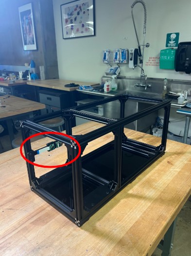
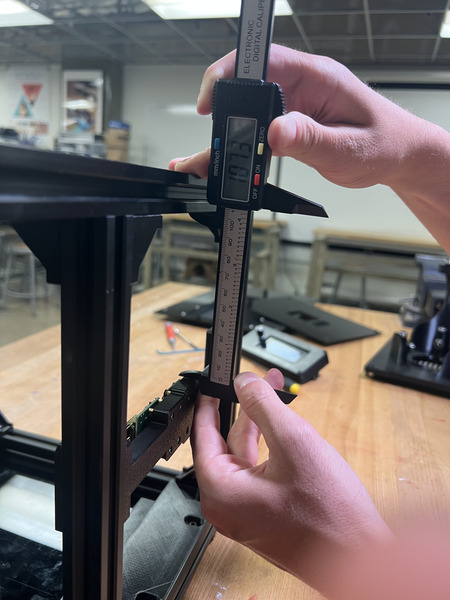
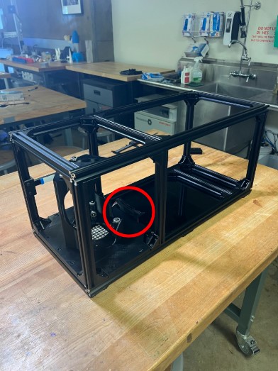
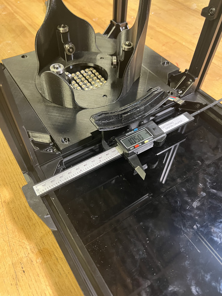
NOTE: Follow the Camera Mount wiring steps linked here first. Install the Camera Mount in the position below. Position it around ~113.6 mm from the bottom of the 3D print to the top of the bottom rail. Tighten the M5 Fasteners.
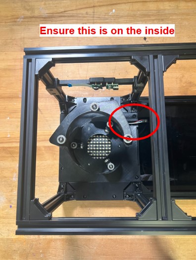
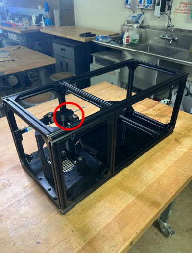
NOTE: Complete the LED wiring section first. Install the Rotation Stage in the position below. The cut-out in the mid base plate should be on the rail in between the vial and projector sections. Ensure the mid base plate is pulled to be flush with the front base plate. Tighten the M5 fasteners. Loosen the screws on the Back Base Plate and bring it as forward as possible. Tighten the M5 fasteners again.

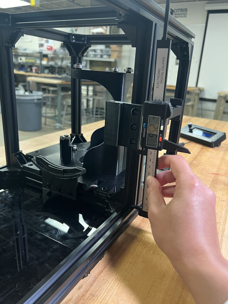
Install the Col Lens Bottom Mount from the Collimating Lens Mounts subassembly in the position below. Position it so the left side of the mount is 105 mm from the front rail. Tighten the M5 fasteners.
Install ONE of the Col Lens Side Mount to the back rail in the position below. Position it so the bottom is 95 mm from the top face of bottom rail of the frame. Tighten the M5 fasteners.
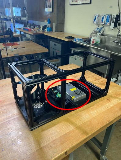
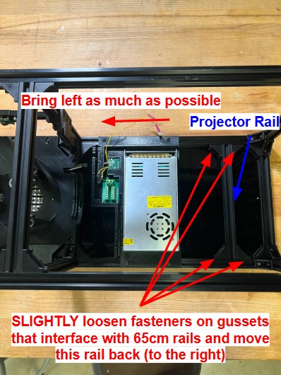
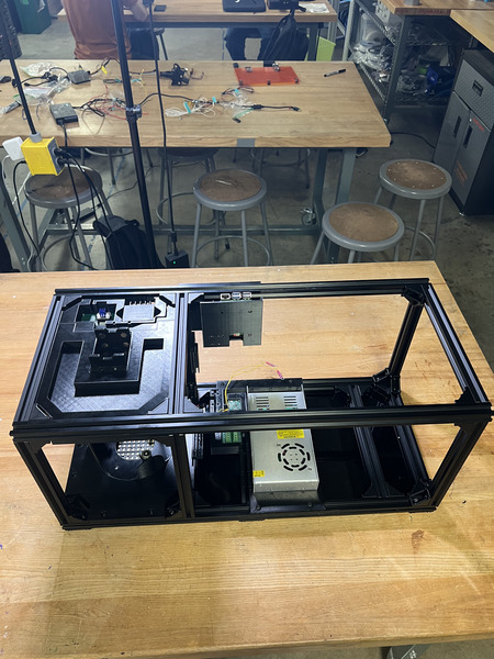
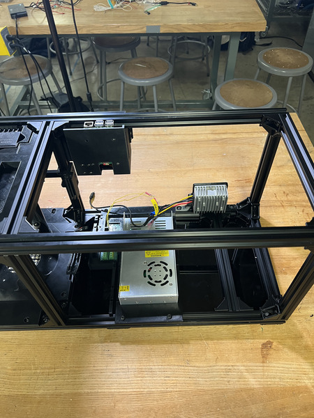
Loosen the M5 fasteners that connect the projector rail (25 cm rail that has 90deg gussets on opposite sides) to the 65 cm rails and move the projector rail closer to the right. Install the electronics Bottom Plate in the position below. Position it as close to the vial section as possible. Tighten the M5 fasteners on the bottom plate. Keep the fasteners on the projector rail loosened.
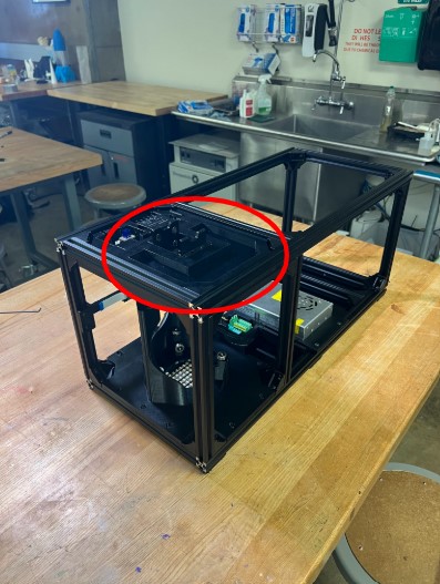
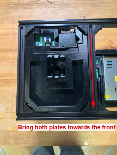
Install the Back Top Plate from the bottom up in the position below. Ensure it is pulled as back as possible. Tighten the M5 fasteners.
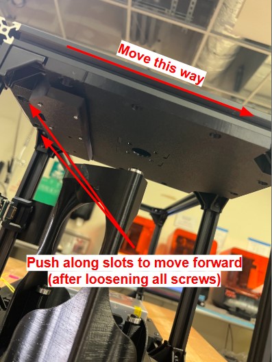
Install the Front Top Plate from the bottom up in the position below. Ensure it is pulled as forward as possible (there should be minimal movement). Tighten the M5 fasteners. Slightly loosen the fasteners on the Back Top Plate and pull it as forward as possible (while ensuring the Hammer TNuts stay in the railing).
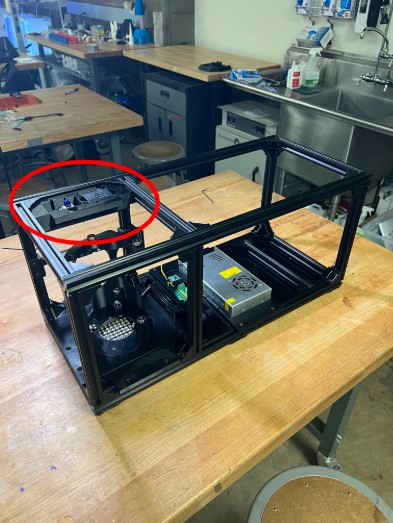
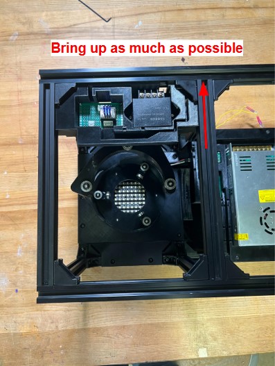
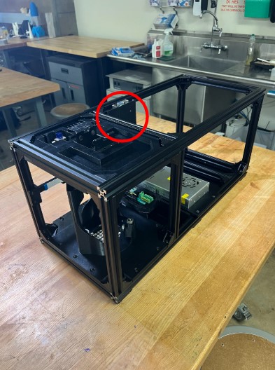
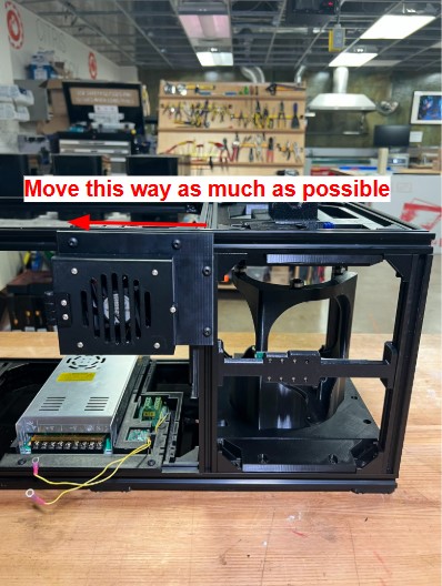
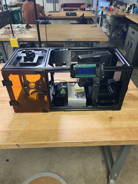
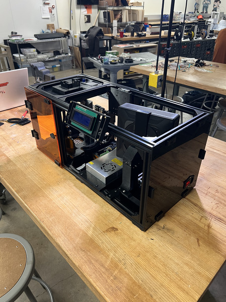
Install the RP5 Housing from the back. You will need to make sure to bring it from the bottom up since this assembly “sandwiches” the rail. Once the RP5 Housing is pulled up and nuts are in the rails, pull it all the way to the left as much as possible (while ensuring the Hammer TNuts stay in the railing). Tighten the M5 fasteners.
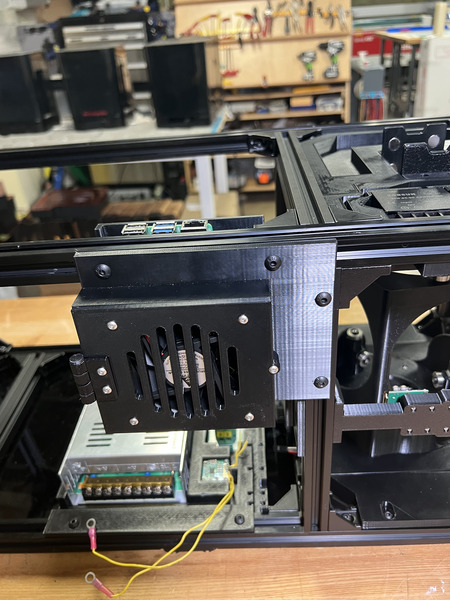
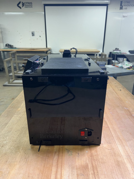
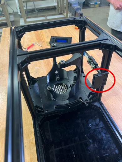
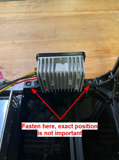
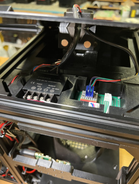
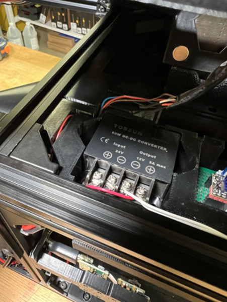
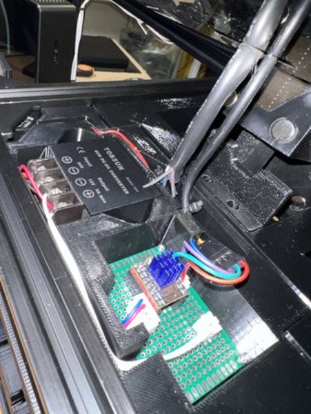
Install the 19V Converter Mount in the position shown below. Tighten the M5 fasteners.
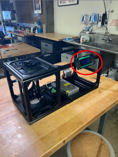
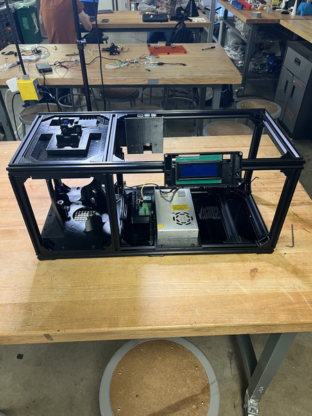
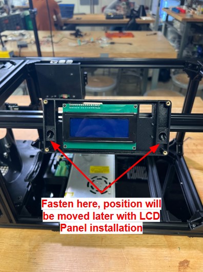
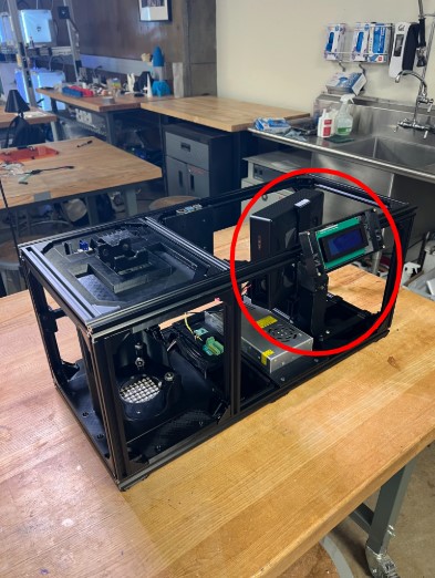
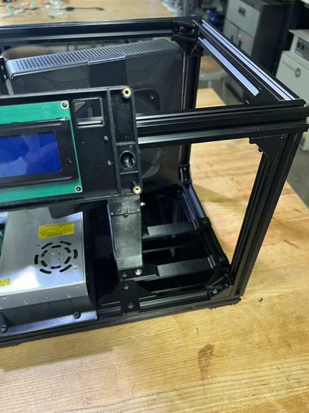
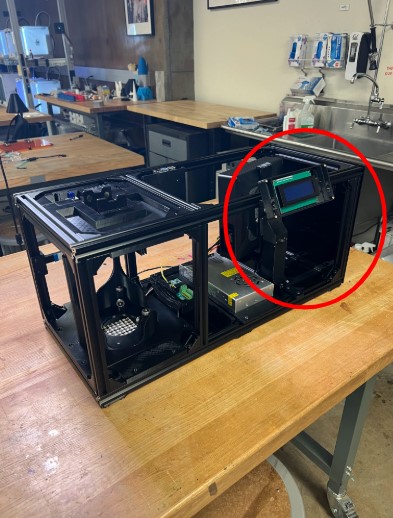
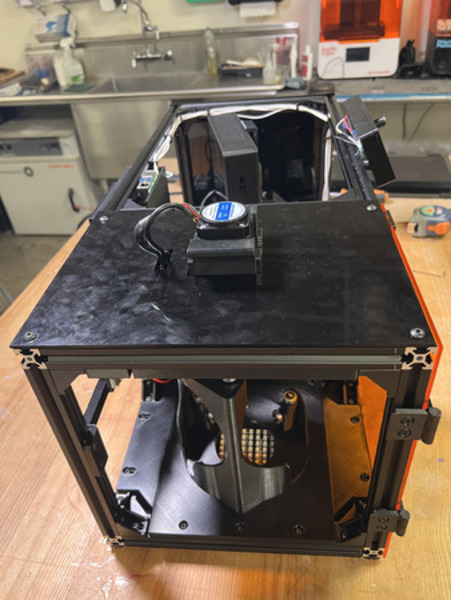
Install the LCD Housing. Ensure the LCD Screen does not fall out. Ensure it is orientated so that the LCD is on the left and encoder area is on the right. Align the nuts on the connector near the position shown below and tighten the M5 fasteners. The position of this housing will slightly change once the LCD Panel is installed in the next phase.
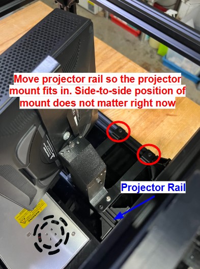
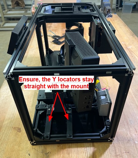
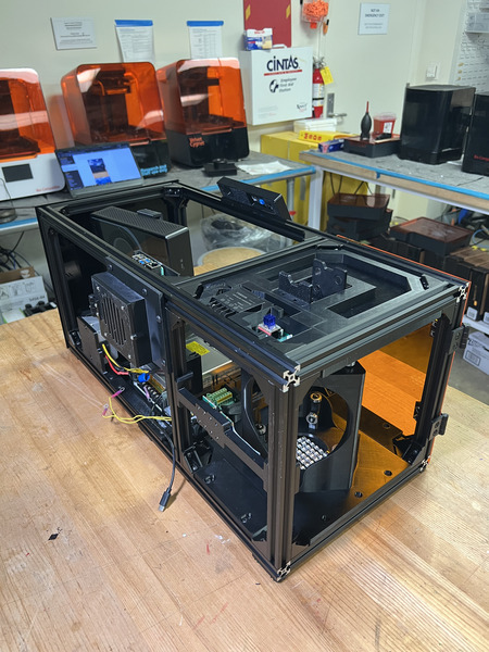
Move the projector rail close to the Bottom Plate from the previous step. Install the Projector Mount, move the projector rail as needed based on the Y locator pieces. Tighten all M5 fasteners.
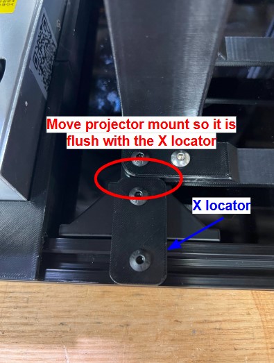
Install QTY (1) X Locator on the front facing side of the projector mount using QTY (2) M5x8 Button Head Screw and QTY (2) M5 Hammer TNut on the opposite end. Loosen the M5 fasteners that interface the rails on the projector mount (2 on the Y Locators on back rail and 2 on the Projector Stand) and move it so it is flush with the X Locator. Tighten all M5 fasteners.
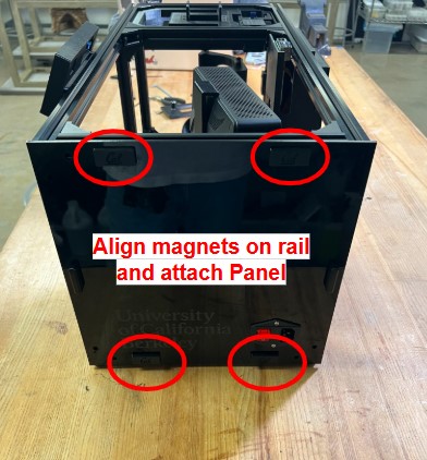
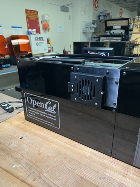
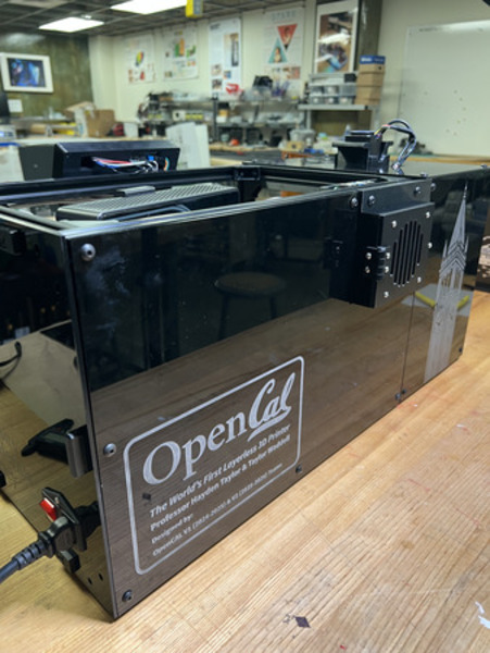
Install the Switch subassembly in the position shown below by aligning the Magnet Frame Inserts in the railing with those on the panel. The top of the panel should touch the top of the frame railing. The exact position will later change once the other panels are on.
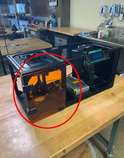
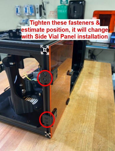
Install the Door subassembly in the position shown below via the short hinges. The bottom of the door panel should be flush with the bottom panel. This position may slightly change when the Side Vial Panel is installed.
Part 1 of the Main Assembly Process is complete.
IMPORTANT: Complete Wiring Instructions before moving on to Part 2.
Main Assembly Process - Part 2
Required Tools:
M3 Hex/Allen Key
Metric Measuring Tape
Digital/Metric Calipers
Note
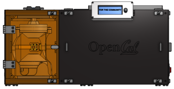
All images show the LCD Top installed on the enclosure. The LCD Top is installed in the LCD Enclosure section of the Wiring portion of the website.
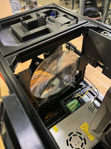
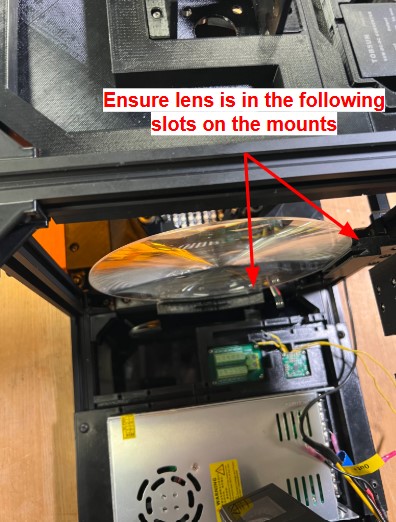
Carefully place in the 200mm Fresnel Lens into the front slots on the collimating lens bottom and side mounts. The flat, non-grooved side of the lens should be facing the projector. See images below.
Now place the Projector Shroud into the other grooves/extrusions of the collimating side mount and the extrusion on the collimating lens bottom mount. The projector shroud can only fit in only one way (one bottom slot, two side slots). The images may not be clear but ensure that the shroud is flush on the Col Lens Bottom Mount and is fully in the side mount.
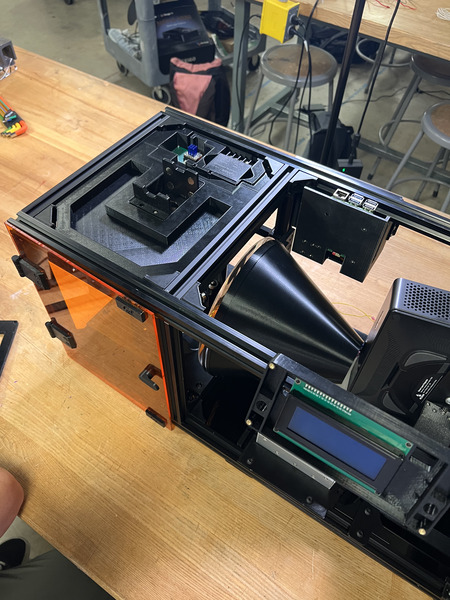
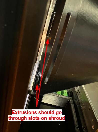
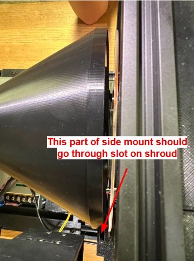
After the projector shroud is in, install the second QTY (1) Col Lens Side Mount on same side but opposite end of the other side mount, ensuring that the 200mm Fresnel Lens is in the first (left) slot, and the Projector Shroud is in the right slot. The Col Lens Side Mount should fit in the Projector Shroud without moving it (should match the height of the other Col Lens Side Mount ~95mm). Tighten all M5 fasteners. See image below.

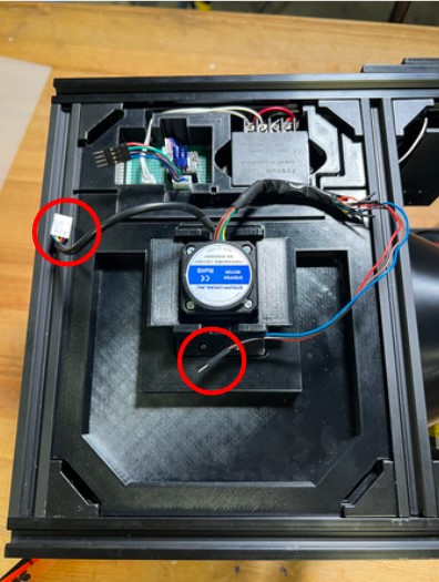
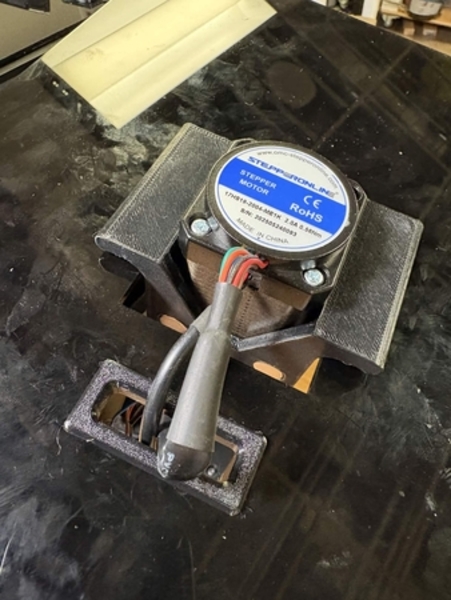
This step is installing the Top Vial Panel Subassembly If the motor and encoder wires are plugged in, disconnect the Dupont connectors. Take off the Stepper Motor Subassembly and run the wires through the cut out in the panel. Place this on top and run the encoder wires through the wire routing cutout in the Top Housing Plate. Reconnect the Dupont connectors for the motor and encoder. Use the zip-tie cutouts to secure the motor and encoder wires. Leave enough slack in the wires for the motor to reach both the “down” and “up” positions. After the wires have been routed, place the panel flat, align the corner M5 Hammer TNuts with the railing and tighten. Ensure the side of the Top Vial Panel is flush with the side face of the rail.
Install the Back Vial Panel Subassembly in the position located below. Ensure that it is flush with the face of the back railing. You may need to loosen the M5 fasteners of the RP5 Housing to push it to the left a little in order to have the Back Vial Panel be flush. After screwing down the Back Vial Panel, bring the RP5 Housing to the right as possible (so it is against the back vial panel) and tighten down.
Install the Back Projector Panel Subassembly by aligning all the M5 Hammer TNuts with their respective rails in the position located below. Tighten all M5 fasteners.
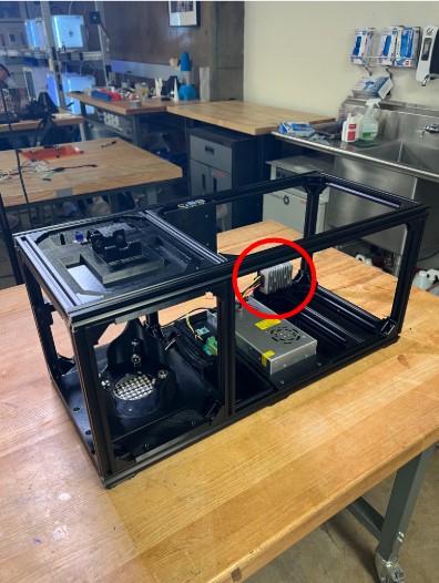
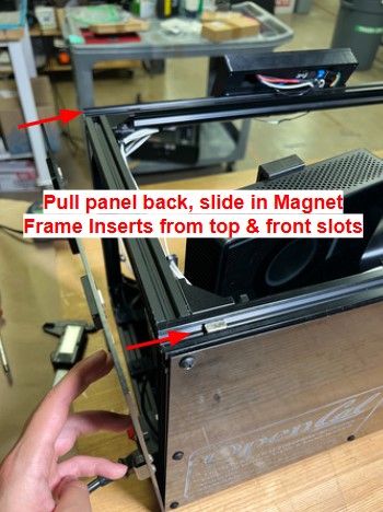
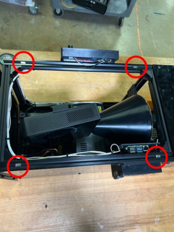
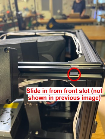
Carefully detach the Switch Subassembly from the magnets and pop it out slightly, ensuring that no wiring gets detached. Slide in QTY (4) Magnet Frame Insert on the top face of the top two 65cm rails (2 each). Place them approximately where you believe it would align with the Top Projector Panel. Then place QTY (1) Magnet Frame Insert on the front top rail (see image below).
(Recommended, not required) Tighten the 4 corner M5 fasteners on the Side Projector Panel, to ensure no wiring comes loose.
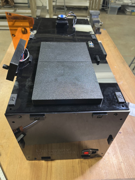
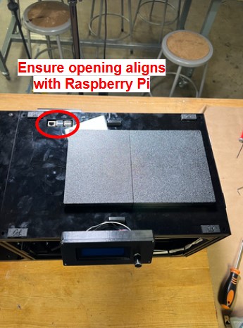
Pop on the Top Projector Panel Subassembly, ensuring the top Magnet Frame Inserts are aligned and it is in the position shown below. Ensure the wiring from the LCD Enclosure does not get caught. It should be orientated so that the CAL logos on the magnet holders are facing the front and the hole for the Pi is aligned.
Open the Door and install QTY (5) Magnet Frame Insert on the front top and bottom rails (3 on each). Place them around the door magnets and around the LCD Panel magnets (see images below).
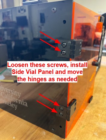
Install the Side Vial Panel Subassembly in the position below. Loosen the M5 fasteners on the Door Hinges that interface with the rail slightly (loose enough that you can move it but it does not fall). Align the Side Vial Panel such that the top of the panel is flush with the top surface of the Top Vial Panel. The back should be flush with the front surface of the Back Vial Panel. Tighten all M5 fasteners, including the ones on the Door Hinges.
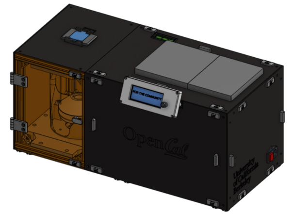
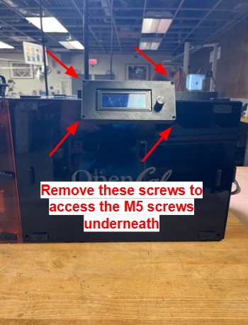
Remove the corner screws on the LCD Top and carefully pull it open and slightly loosen the ‘2’ M5 fasteners that connect the LCD Enclosure to the rail (so that it can move but does not come off). Pop on the LCD Panel Subassembly by aligning it with the magnet frame inserts from the previous step and move the LCD Enclosure as needed. The right side of the LCD Panel should be flush with the BACK surface of the Side Projector Panel. Once the LCD Panel is in place, tighten the the two M5 fasteners on the LCD Enclosure and reinstall the 4 corner screws on the LCD Top.
OpenCAL is complete.