Tomo: Workflow & Controls
Tomo is organized as five numbered tabs that mirror the CAL pipeline; you move left to right through them (with Back / Next buttons) to take a model from STL to a print-ready projection video:
1·Vial → 2·Model → 3·Voxelize → 4·Optimize → 5·Output
A persistent top bar holds actions and presets that apply across the whole job.
Top Bar
Control |
What it does |
|---|---|
Start New Part |
Clears the current part and parameters to begin a fresh job. |
Load run |
Reloads a previously saved run, restoring all of its parameters. |
Materials ▾ |
Manage resin material presets. Each material stores a refractive index (n), an
Absorption setting (on/off + attenuation coefficient |
Settings ▾ |
Application settings (see below). |
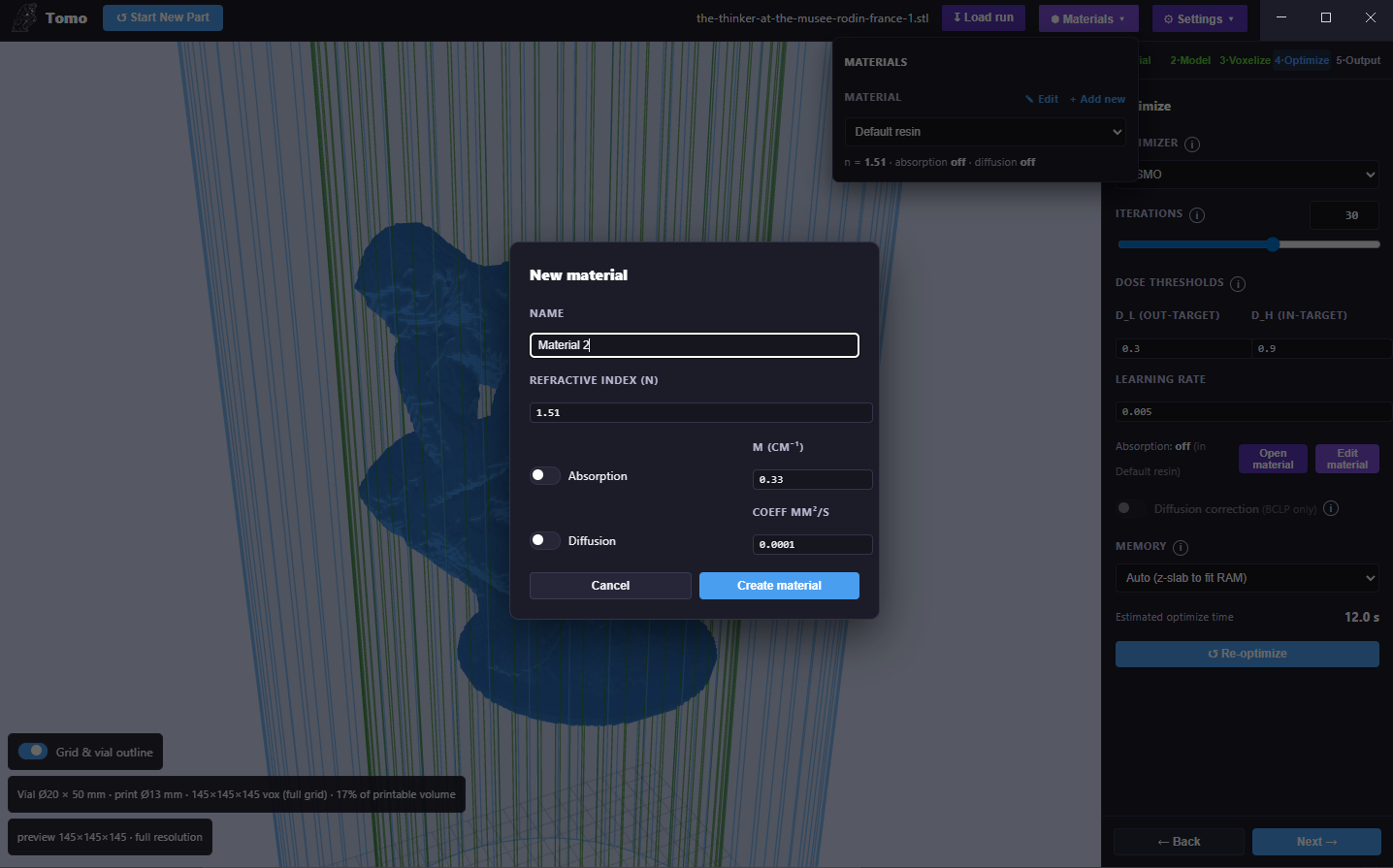
The Materials menu with the “New material” dialog — set the refractive index, absorption (μ), and diffusion coefficient.
Settings menu
Use GPU (CUDA) — run voxelization/optimization on the GPU (recommended).
Verbose optimization output — show the live four-panel diagnostic while optimizing.
Auto-scale suggestions — offer to scale a part to fit the vial.
Also save reloadable project (.tomo) — save a reloadable project file alongside outputs.
Video frames per degree — projection-video sampling density.
Export / Import all custom settings, Export log, plus a machine readout (GPU, cores, RAM). Debug logs are kept under
logs/and optimize timing accumulates inoptimize_times.csv.
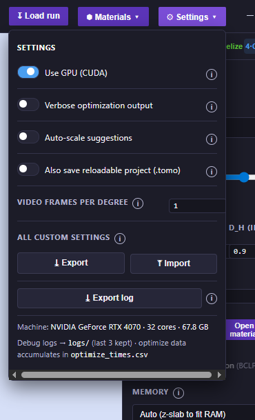
The Settings menu.
Stage 1 — Vial
Choose the resin container and define the printable volume.
Vial size — pick a preset (e.g. Small — Ø20 × 50 mm), or Edit / + Add new to define your own (name, height, diameter).
Vial correction — when enabled, Tomo models refraction at the vial wall, which shrinks the usable printable region to the green inner cylinder shown in the 3D view (for the Ø20 mm vial, a usable radius of ≈ 6.6 mm / Ø13 mm). Keep your part inside the green cylinder.
The 3D view shows the blue vial outline, the green printable cylinder, and a reference grid (toggle with Grid & vial outline).
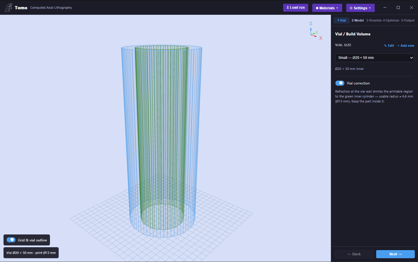
Stage 1 · Vial — vial-size preset, the Vial correction toggle, and the blue vial outline with the green printable cylinder.
Stage 2 — Model
Load and place your part.
Add STL(s) / Remove — load one or more STL files.
Transform tools (left toolbar): Select, Move, Rotate, Scale — with keyboard shortcuts W (move), E (rotate), R (scale).
Position (mm), Rotation (°), and Scale (per-axis, with an optional uniform lock). A live Size readout shows the current bounding box in millimetres.
Auto-scale (fit the part to the vial), Center, and Reset buttons.
Tomo warns if the part’s footprint exceeds the printable radius.
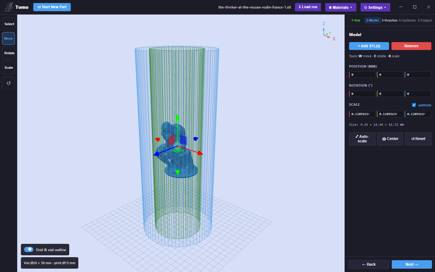
Stage 2 · Model — an STL loaded with the transform gizmo and the Position / Rotation / Scale panel.
Stage 3 — Voxelize
Convert the mesh into a high-resolution voxel target.
Projector — pick a projector preset (e.g. OpenCAL V2), or Edit / + Add new. The preset defines the resolution in pixels (width × height), the pixel pitch (µm), the resulting build area (mm), and whether the projector is telecentric or has a finite throw ratio. This sets the print resolution.
Resolution scale — a slider that trades detail for speed/memory. Tomo shows the effective pitch vs the full pitch, the approximate voxel-count reduction, the estimated grid size, the voxel count, and the voxelize time.
Re-voxelize runs the GPU layer-slicer; the result line reports the final grid (e.g.
145×145×145) and the fill % of the printable volume, with a live 3D voxel preview.
Note
High resolution is never silently coarsened; if you ask for a fine pitch, Tomo voxelizes at that pitch. The resolution-scale reduction is opt-in.
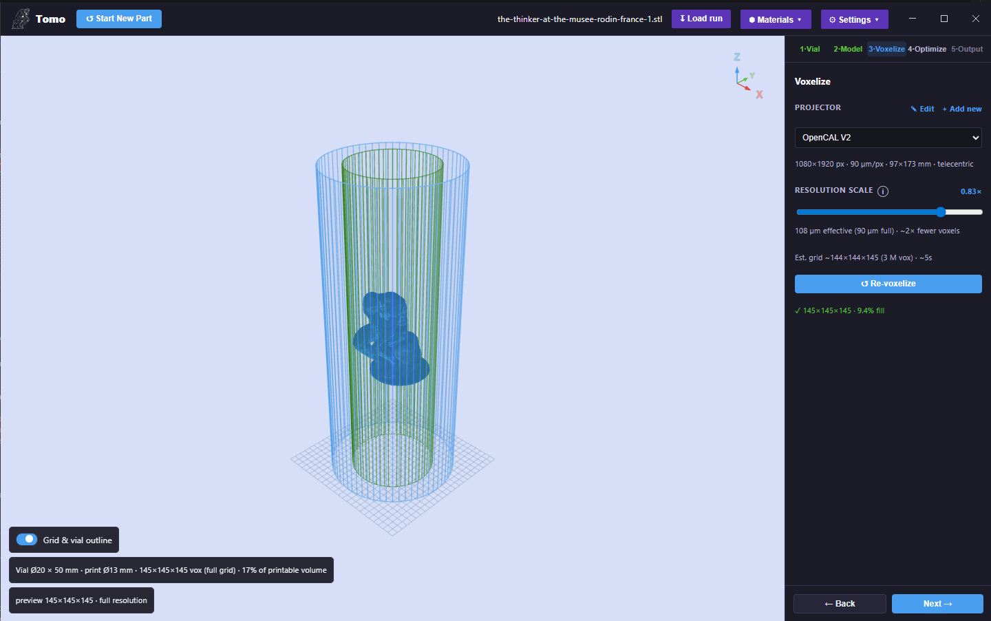
Stage 3 · Voxelize — the projector preset, the resolution-scale slider with its live estimate, and the voxel preview.
Stage 4 — Optimize
Compute the sinogram (the projection sequence) with the tomographic optimizer.
Control |
What it does |
|---|---|
Optimizer |
OSMO (Object-Space Model Optimization — fast threshold optimizer for solid/binary parts) or BCLP (Band-Constrained Linear Programming — handles grey/continuous targets and is required for diffusion correction; ~1.4× slower). |
Iterations |
Number of optimization passes — slider plus a free-entry number field. |
Dose thresholds (D_L / D_H) |
Normalized dose targets (0–1). D_H (in-target) is the minimum dose that must be reached inside the part (gel point); D_L (out-target) is the maximum dose allowed outside it. A wider D_H–D_L gap is more robust but harder to hit. |
Learning rate |
Gradient step size for the BCLP optimizer. |
Absorption |
Beer–Lambert attenuation compensation, driven by the active Material preset. Use Open material / Edit material to change it. |
Diffusion correction |
Compensates for cure/diffusion blur (sharper edges). BCLP only — auto-disabled for OSMO. |
Memory |
z-slab mode: Auto (z-slab to fit RAM), Off, or a fixed slab count — lets very large optimizations fit in RAM. |
Tomo shows an estimated optimize time, then Optimize runs the solve. With Verbose optimization output enabled, a live “Optimizing print” window shows the current iteration / total, the dose error, and a four-panel diagnostic (the target slice, the predicted-dose reconstruction, an error-vs-iterations curve, and the dose distribution histogram), with a Cancel button.
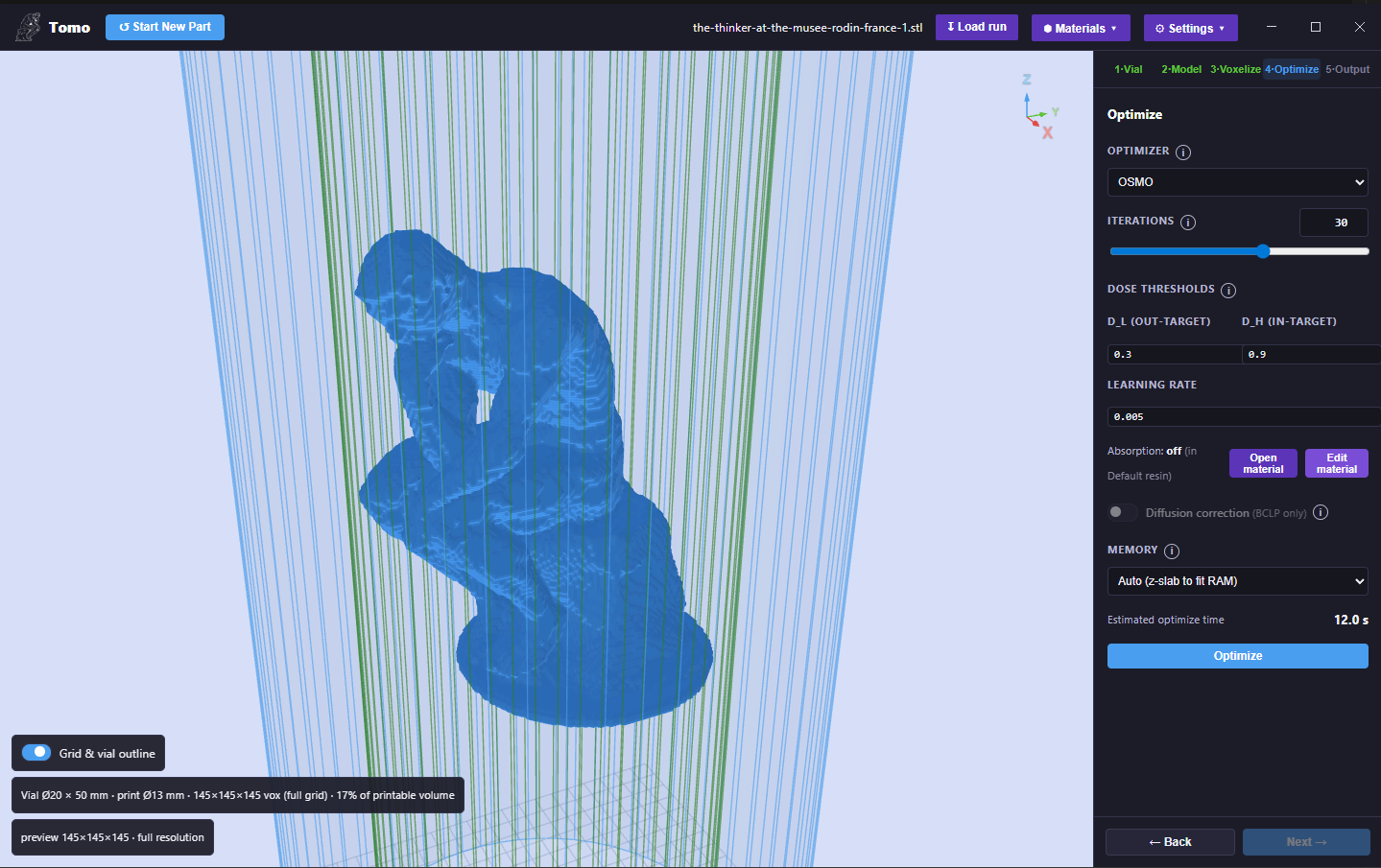
Stage 4 · Optimize — optimizer, iterations, dose thresholds (D_L / D_H), learning rate, diffusion, and memory.
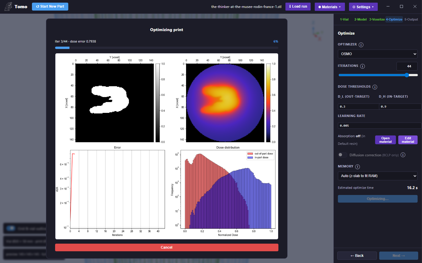
The live “Optimizing print” window (verbose output) — target slice, predicted-dose reconstruction, error curve, and dose histogram.
Stage 5 — Output
Preview the result and export the print.
Projection video — play the optimized sinogram as a rotating, looped projection video (one rotation, N frames). This is the exact image sequence the projector plays. Intensity and Zoom controls adjust the preview.
Video length (min) — sets the print duration encoded into the exported video.
Print Quality panel:
Process window — a single score. Positive means a single dose threshold cures the part cleanly; negative means dose overlap (some stray cure is unavoidable), so try more iterations or widen the D_H–D_L gap.
Dose distribution — a histogram of in-part (blue) vs out-of-part (red) voxel doses, with the gel-dose threshold marked. A clean gap between the two humps is ideal.
Reconstruction (predicted dose, mid-slice) — the simulated cured cross-section.
Final dose error — overall dose-matching error metric.
Save run — persist the job and all its parameters (reload later with Load run). Export the projection video as MP4.
Tip
Name the exported print file using the OpenCAL convention so the printer reads the RPM
automatically, e.g. part_9rpm.mp4; see Video File Naming Convention.
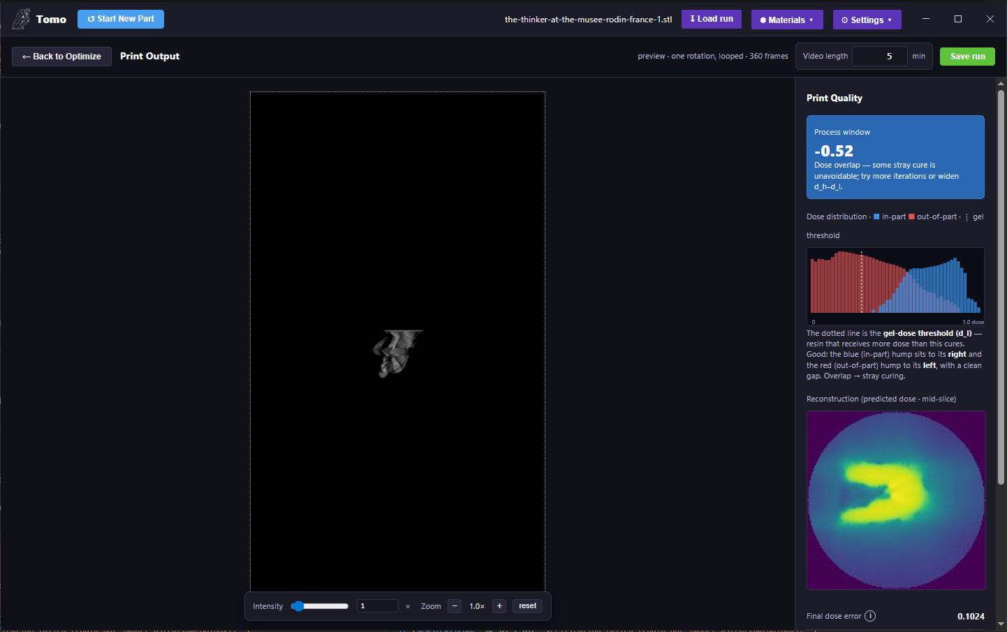
Stage 5 · Output — the projection-video preview and the Print Quality panel (process window, dose histogram, reconstruction, final dose error).
Hardware
Tomo auto-detects your CUDA GPU and tunes the run for it (the detected machine is shown in the Settings menu); CUDA is used when available, with a CPU fallback. A GPU is strongly recommended for full-resolution voxelization and optimization.