Electronics Subassemblies
The electronics consists of the following subassemblies:
Bottom Plate
Top Plate
LCD Housing
19V Converter Assembly
Raspberry Pi Housing
Camera Mount
Switch
NOTE: This is ONLY for electronic mounting. Wiring will occur in another page.
Bottom Plate
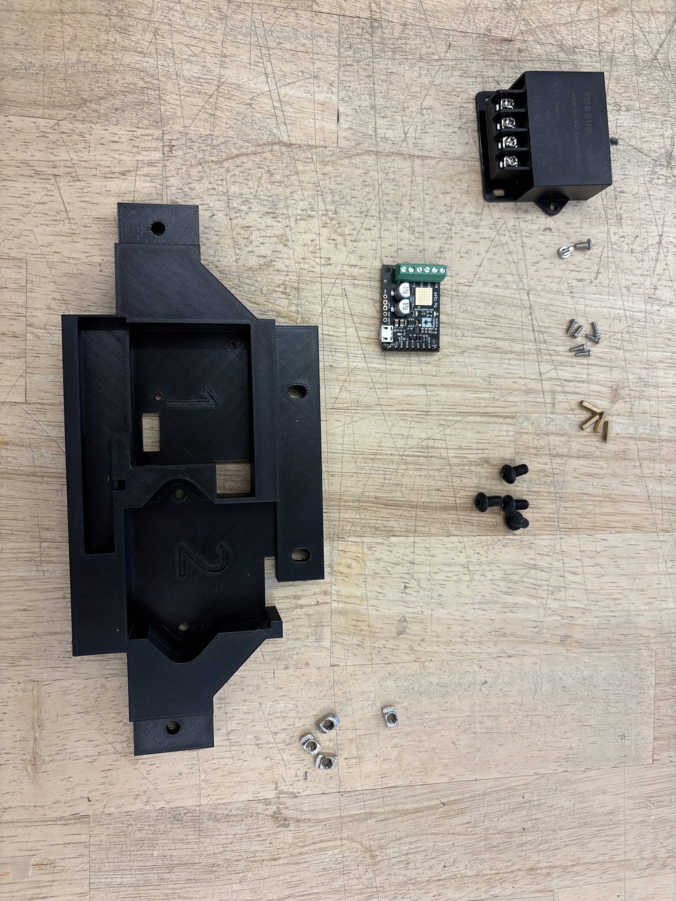
Required Materials:
NOTE: Heat Set Insert has already been installed into the Bottom Plates.
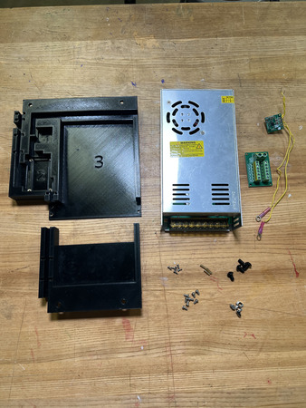
(QTY 1) Bottom Plate 1
(QTY 1) Bottom Plate 2
(QTY 1) 24V Power Supply
(QTY 1) 5V Buck Converter
(QTY 1) Terminal Block
(QTY 3) M2x10 Standoffs
(QTY 6) M2x6 Button Head Screw
(QTY 8) M3x4x5 Heat Set Insert
(QTY 8) M3x6 Button Head Screw
(QTY 4) M5x10 Button Head Screw
(QTY 4) M5 Hammer TNut
Required Tools:
Soldering Iron
M2 Hex/Allen Key
Small Phillips Driver (+1.5)
Step-by-Step Instructions
NOTE: Unless otherwise mentioned, all fasteners will be “hand tight”. Ensure that heat set inserts have ~2 minutes to cool post installation.
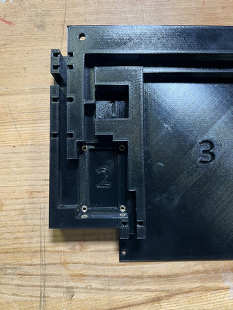
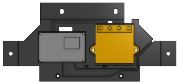
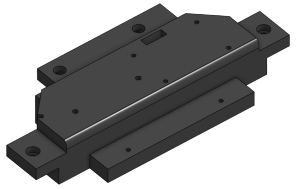
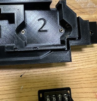
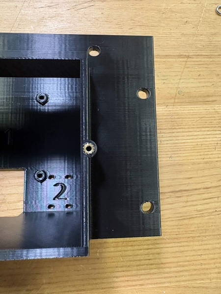
Take the QTY (1) Bottom Plate 2 and flip it so that it is laying on the top. Take QTY (4) M3x4x5mm Heat Set Insert and, using a soldering iron, place them into the following locations on the Bottom Plate 2. Ensure that the top of the heat set inserts are flush with the surfaces.
Take QTY (4) M3x4x5mm Heat Set Insert and, using a soldering iron, place them into the following locations on the QTY (1) Bottom Plate 1 (in the ‘2’ area). Ensure that the top of the heat set inserts are flush with the surfaces.
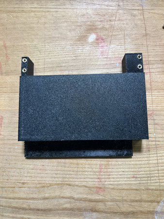
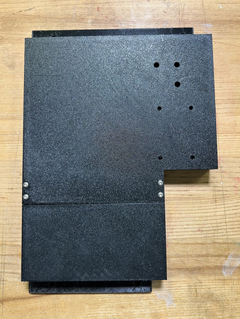
Flip the QTY (1) Bottom Plate 1 and align it with QTY (1) Bottom Plate 2. Fasten down the plates using QTY (4) M3x6 Button Head Screw using a M2.5 Hex/Allen Key.
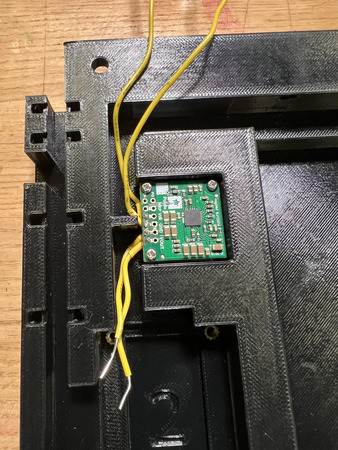
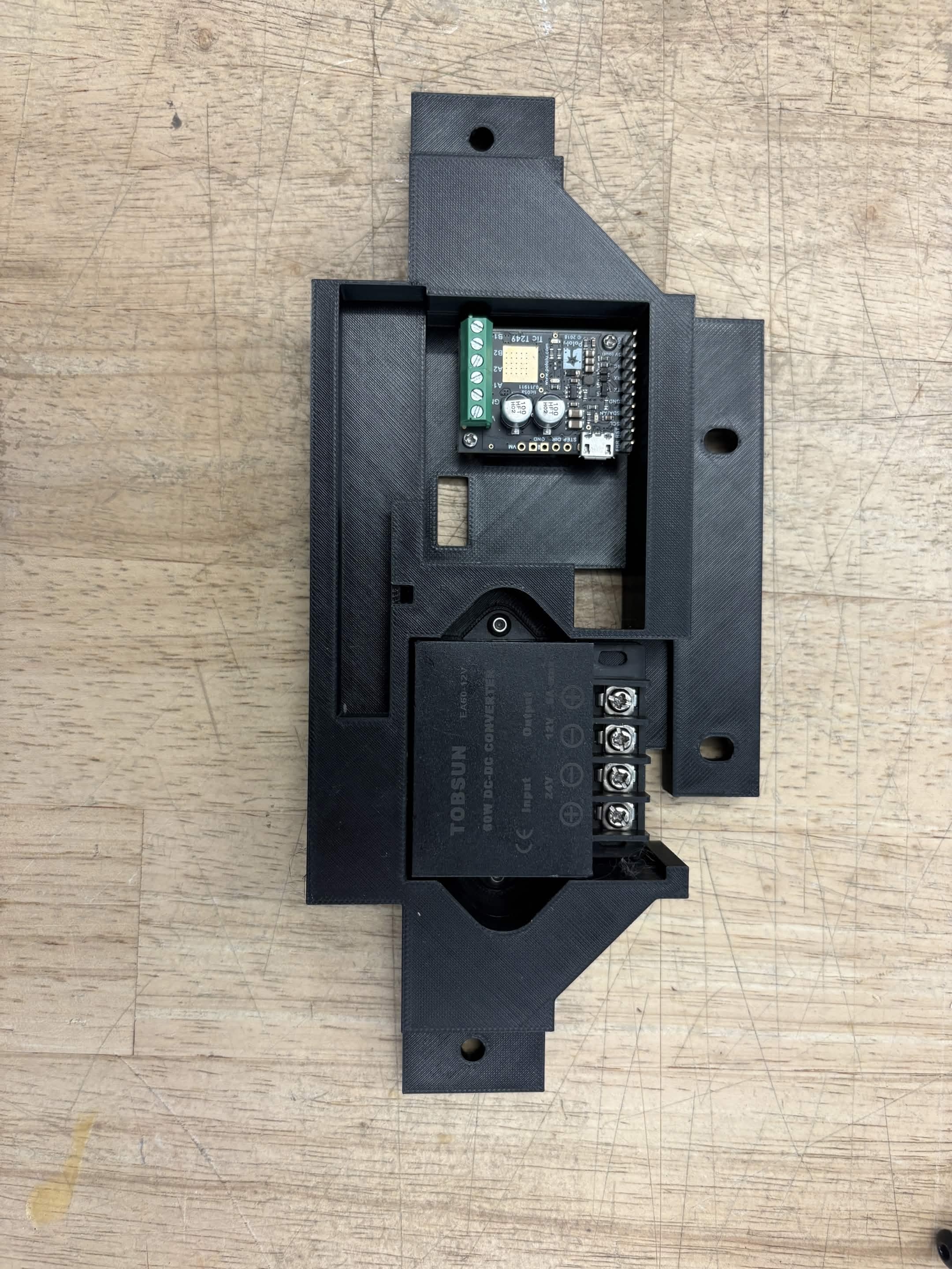
Install QTY (1) 5V Buck Converter onto QTY (3) M2x10 Standoff using QTY (3) M2x6 Button Head Screws from the front (screws should be going from converter to standoffs).
In the ‘1’ area, install the assembly from Step 4 by placing it in the designated locations and screwing them in with QTY (3) M2x6 Button Head Screw on the opposite end of the Bottom Plate 1. Ensure that it is orientated where the wires are coming out on the left of the ‘1’.
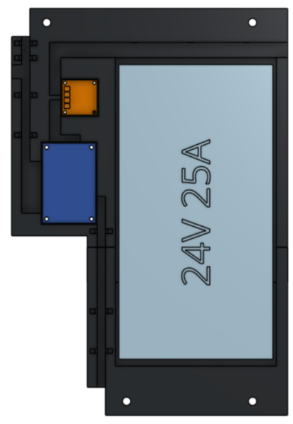
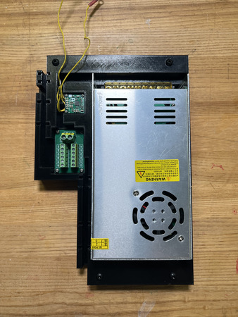
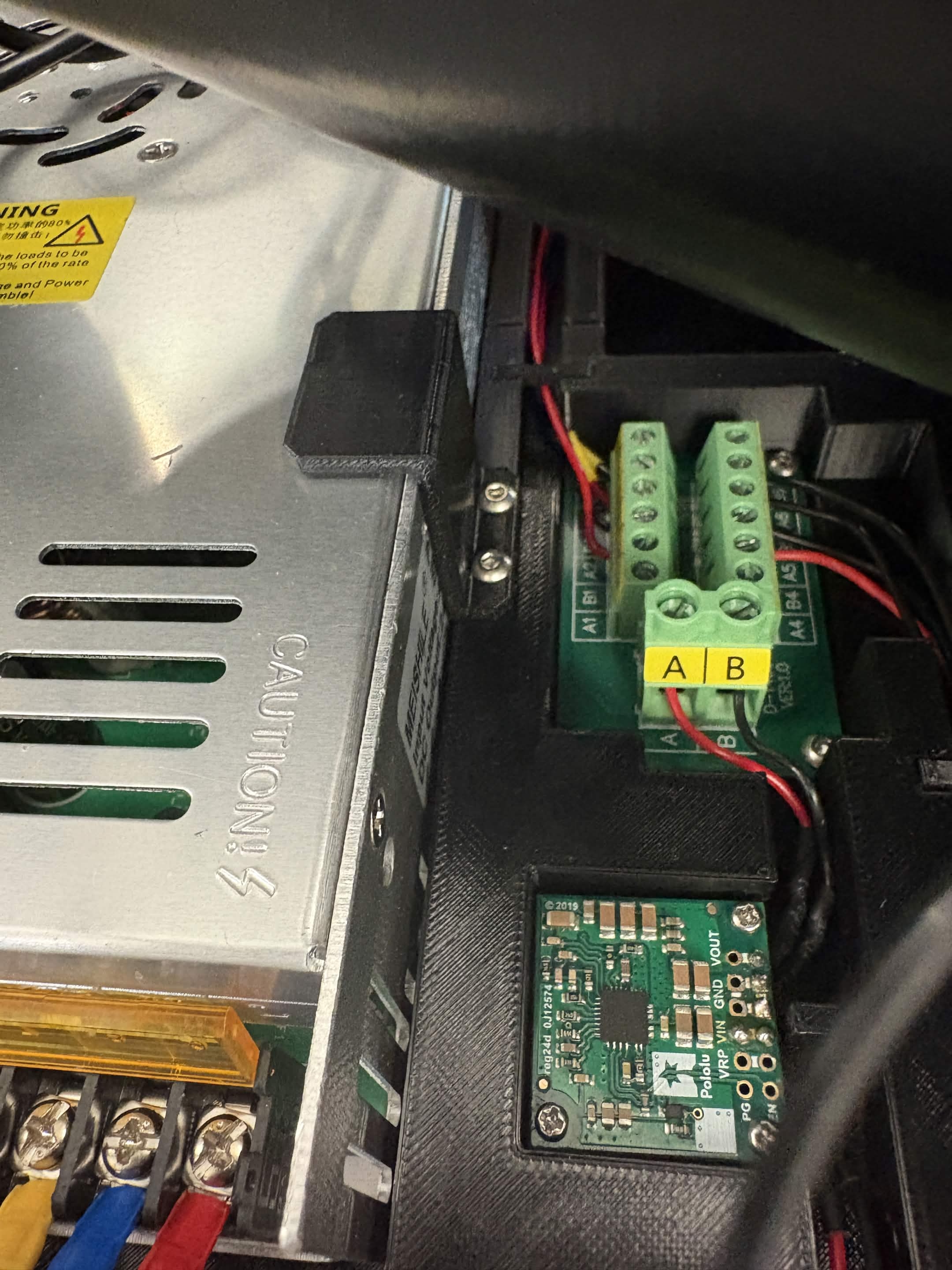
Take the QTY (1) Terminal Block and install it in section ‘2’ using QTY (4) M3x6 Button Head Screw. Ensure that it is orientated where the AB screw terminals are facing the 5V Buck converter (see image below).
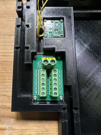
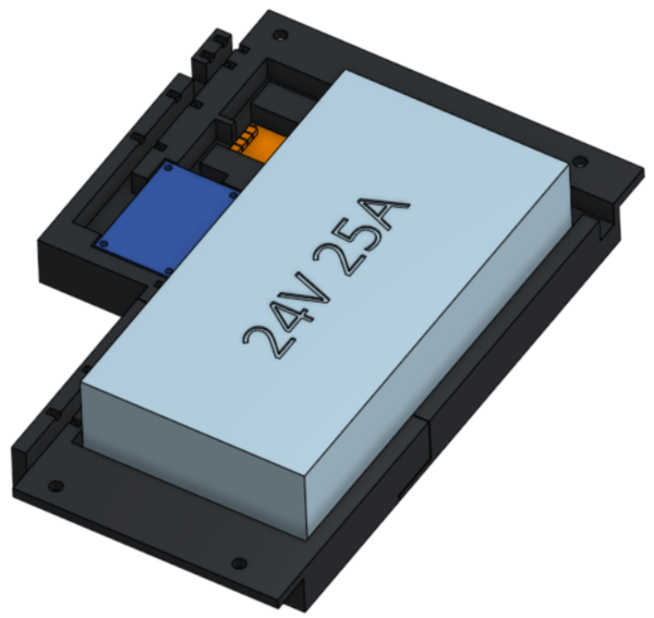
Take the QTY (1) 24V Power Supply and place it in section ‘3’. Ensure that it is orientated where the wires would be coming out from the top. This will not be fixed down due to its weight.
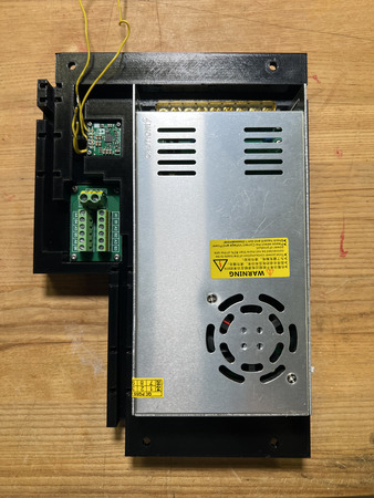
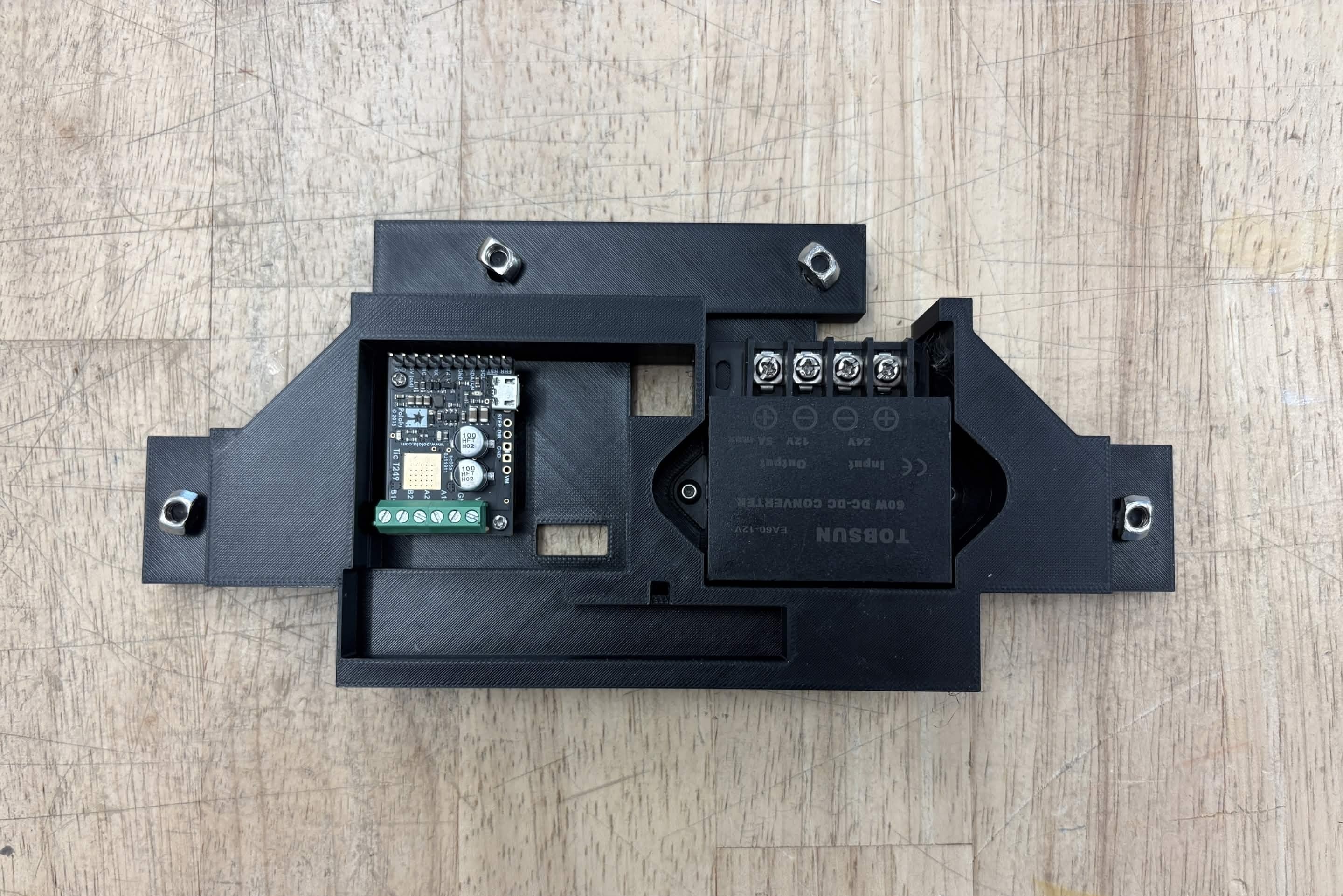
Place QTY (4) M5x10 Button Head Screw through each of the holes on the QTY (1) Bottom Plate 1 and QTY (1) Bottom Plate 2 from the top. Loosely install QTY (4) M5 Hammer TNut on the opposite ends.
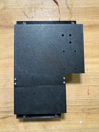
The Bottom Plate is now complete. Note: In an updated version of the bottom plate, clamps can be added to hold down the 24V Adapter using M3 heat sets and screws.
Top Plate
Required Materials:
NOTE: Heat set inserts were already installed into the Back Top Plate
(QTY 1) Back Top Plate
(QTY 4) M2x10 Standoffs
(QTY 8) M2x6 Button Head Screws
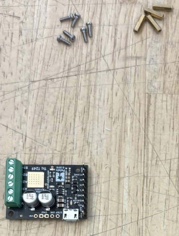
(QTY 1) Tic T249
(QTY 1) 12V Buck Converter
(QTY 2) M3x4x5 Heat Insert
(QTY 2) M3x6 Button Head Screw
Required Tools:
Soldering Iron
M2 Allen/Hex Key
Small Phillips Driver (+1.5)
Step-by-Step Instructions
NOTE: Unless otherwise mentioned, all fasteners will be “hand tight”. Ensure that heat set inserts have ~2 minutes to cool post installation.
Take QTY (2) M3x4x5mm Heat Set Insert and, using a soldering iron, place them into the following locations on the QTY (1) Top Plate (in the ‘2’ area). Ensure that the top of the heat set inserts are flush with the surfaces.
Attach the QTY (1) Tic T249 onto QTY (2) M2x10 Standoffs using QTY (2) M2x6 Button Head Screws from the top (screws should be going from Perfboard Assembly to standoffs).
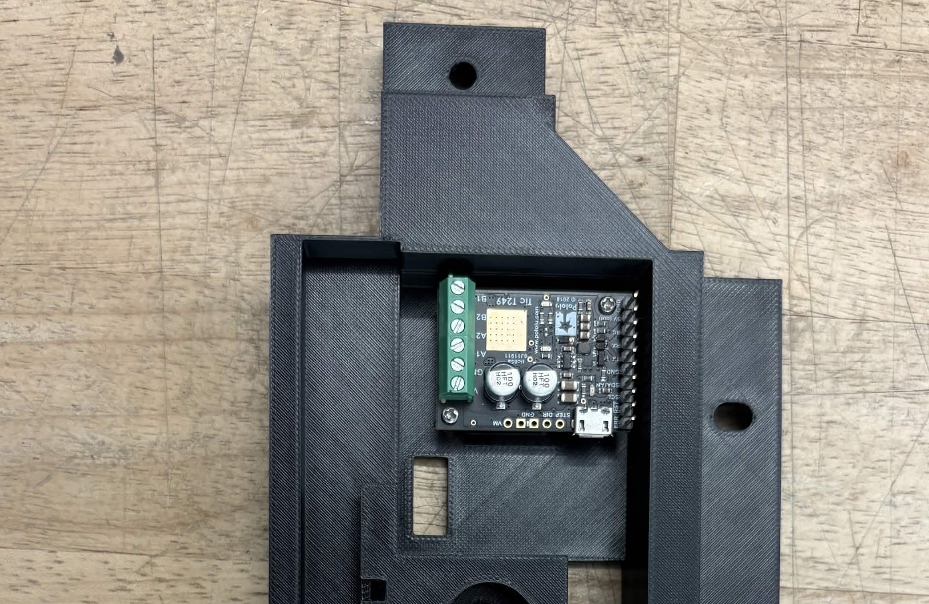
Take the assembly from Step 2 and install it in section ‘1’, using QTY (2) M2x6 Button Head Screw from the opposite end of the Top Plate. Ensure that it is orientated where the motor circuit is closer to the right side of the ‘1’ on the 3D print.
Take QTY (1) 12V Buck Converter and install it in section ‘2’, using QTY (2) M3x6 Button Head Screw. Ensure that it is orientated where the screw terminals are on the top (see image).
Place QTY (4) M5x10 Button Head Screw through each of the holes on the QTY (1) Top Plate from the BOTTOM. Loosely install QTY (4) M5 Hammer TNut on the opposite ends.
The Top Plate is now complete.
LCD Housing


Required Materials:
NOTE: Heat set inserts had already been installed into the LCD Base. The Knob Encoder mounting Washer & Nut should come with the Knob Encoder kit.
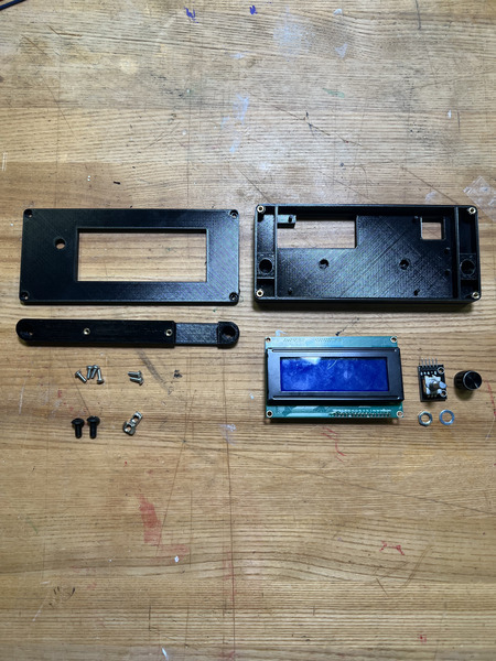
(QTY 1) LCD Base
(QTY 1) LCD Connector
(QTY 1) LCD Top
(QTY 1) LCD Screen
(QTY 1) Knob Encoder
(QTY 1) Knob Encoder Washer
(QTY 1) Knob Encoder Nut
(QTY 6) M3x6x5 Heat Set Insert
(QTY 6) M3x8 Button Head Screw
(QTY 2) M5x8 Button Head Screw
(QTY 2) M5 Hammer TNut
Required Tools:
M3 Hex/Allen Key
M2 Hex/Allen Key
Step-by-Step Instructions
NOTE: Unless otherwise mentioned, all fasteners will be “hand tight”.
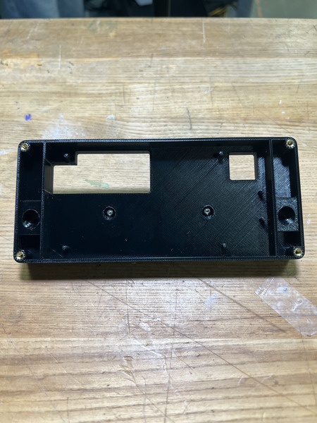
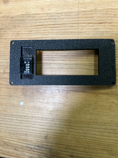
Take QTY (4) M3x6x5mm Heat Set Insert and, using a soldering iron, place them into the following locations on the QTY (1) LCD Base from the front. Ensure that the top of the heat set inserts are flush with the surfaces.
Take QTY (2) M3x6x5mm Heat Set Insert and, using a soldering iron, place them into the following locations on the QTY (1) LCD Connector from the front. Ensure that the top of the heat set inserts are flush with the surfaces.
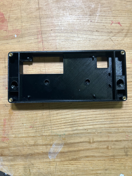
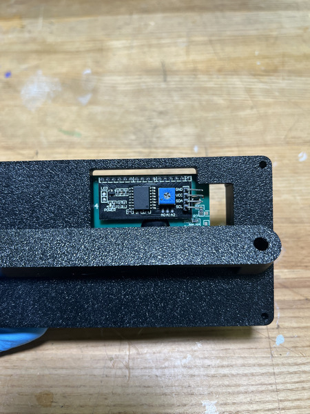
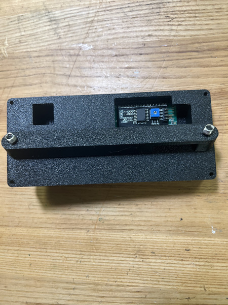
Install the QTY (1) LCD Connector using QTY (2) M3x8 Button Head Screw. The connector should be oriented so that the cutout is under the big cutout on the LCD Base (see image). The screws should be going through the LCD Base from the center counterbores and into the connector.
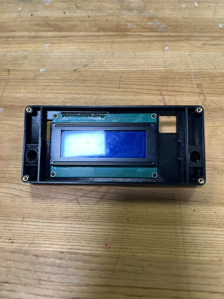
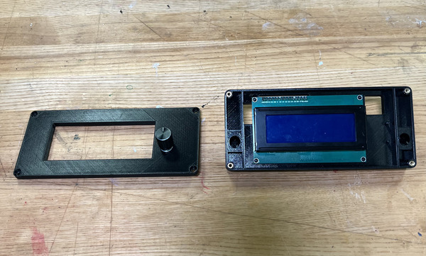
Install the QTY (1) LCD Screen by aligning its holes with the small extruded pillars on the QTY (1) LCD Base and pressing down. Ensure the LCD screen is on the left position. Ensure the PCB of the LCD comes out the back.
Slide QTY (2) M5x8 Button Head Screw through the holes on the side of the LCD Base. Loosely install QTY (2) M5 Hammer TNut to the other side.
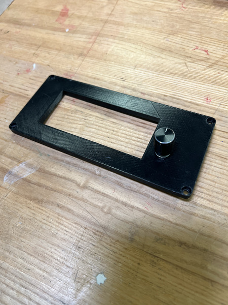
Pull out the knob of the QTY (1) Knob Encoder and keep it to the side. Also unscrew the QTY (1) Knob Encoder Nut and QTY (1) Knob Encoder Washer if it is attached. Take the QTY (1) LCD Top and place the encoder from the back end through the designated hole on the right of the large rectangular cutout. Ensure the prongs of the encoder face up. While pressing the encoder against the LCD Top from the back, place on the washer and tighten down the nut onto the encoder to lock it in place.
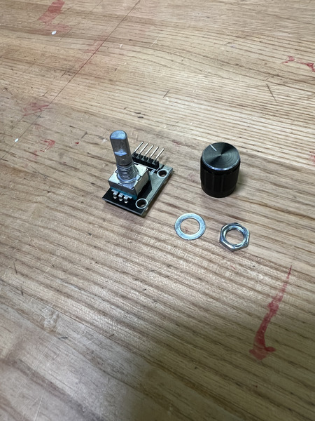
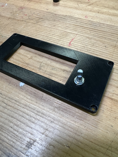
Press on the Knob onto the Knob Encoder. NOTE: This will fix the encoder to the top lid.
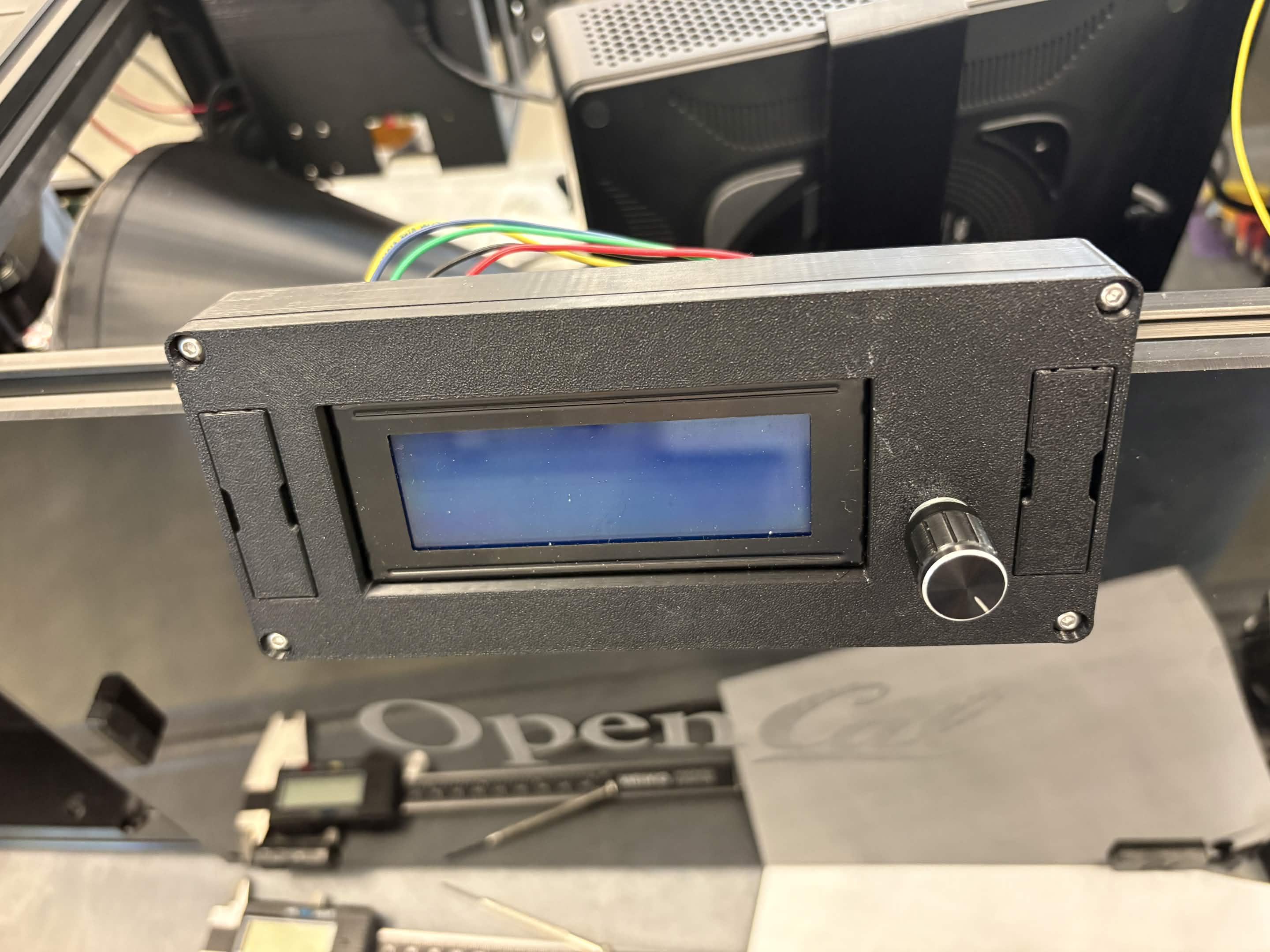
The LCD Enclosure is now complete. Note: in a new version of the LCD top, press fit covers can be removed for access to the screws connected to the extrusion frame.
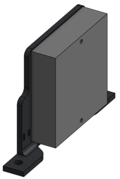
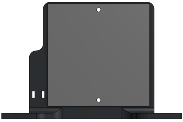
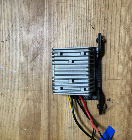
19V Converter Assembly
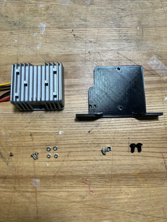
Required Materials:
(QTY 1) 19V Converter Mount
(QTY 1) 19V Buck Converter
(QTY 2) M3x10 Button Head Screw
(QTY 2) M3 Washer
(QTY 2) M3 Hex Nut
(QTY 2) M5x8 Button Head Screw
(QTY 2) M5 Hammer TNut
Required Tools:
M2 Hex/Allen Key
Step-by-Step Instructions
NOTE: Unless otherwise mentioned, all fasteners will be “hand tight”.
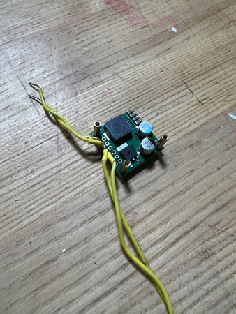
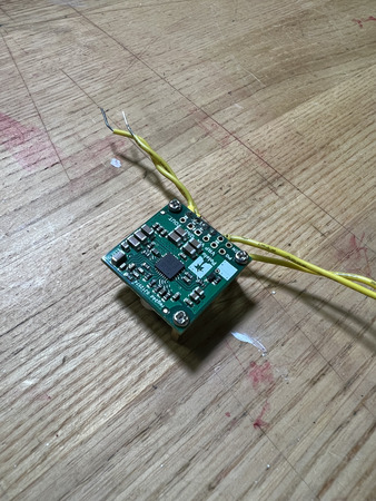
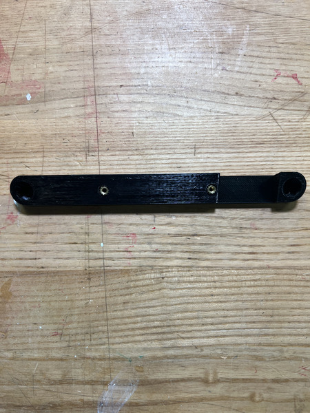
Place the flat end of the QTY (1) 19V Buck Converter against the non-counterbored side of the QTY (1) 19V Converter Mount with the wires going to the left. Fasten these together using QTY (2) M3x10 Button Head Screw, QTY (2) M3 Washer, and QTY (2) M3 Hex Nut from the opposite end. Ensure the fastener comes from the 3D printed side and the washer is under the head of the fastener (the fastener and washer should be in the counterbore).
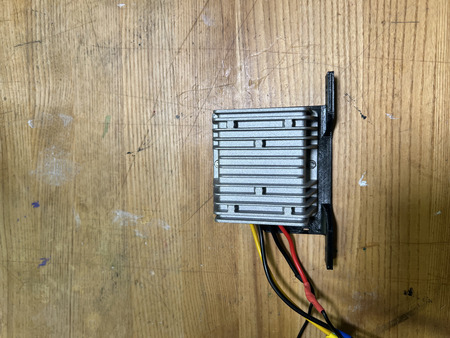
Insert QTY (2) M5x8 Button Head Screw from the top on each of the side mounting points as shown below. Loosely install QTY (2) M5 Hammer TNut on the opposite end of each fastener.
The 19V Converter Assembly is now complete.
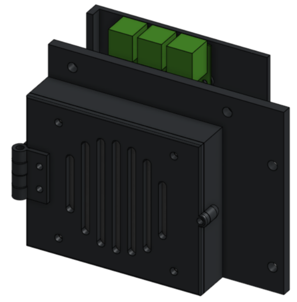
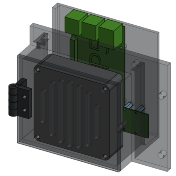
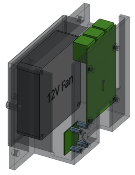
Raspberry Pi Housing
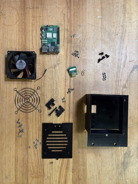
Required Materials:
NOTE: Heat set is already installed into RP5 Housing. M2 Hex Nuts are missing from image.
(QTY 1) RP5 Housing
(QTY 1) Raspberry Pi 5
(QTY 1) RP5 Housing Door
(QTY 2) RP5 Door Hinge
(QTY 1) Hinge Pin
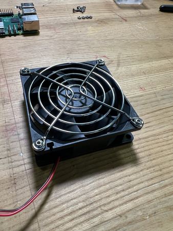
(QTY 1) Brushless Cooling Fan
(QTY 1) CSI to HDMI Adapter
(QTY 4) M2x10 Standoff
(QTY 12) M2x6 Button Head Screw
(QTY 1) M3x8 Button Head Screw
(QTY 12) M3x10 Button Head Screw
(QTY 4) M2 Hex Nut
(QTY 12) M3 Hex Nut
(QTY 4) M5x10 Button Head Screw
(QTY 4) M5 Hammer TNut
(QTY 1) M3x4x5mm Heat Set Insert
(QTY 4) M2x4x3.2mm Heat Set Insert
Required Tools:
M2 Hex/Allen Key
M3 Hex/Allen Key
Soldering Iron
Small Phillips Driver (+1.5)
Step-by-Step Instructions
NOTE: Unless otherwise mentioned, all fasteners will be “hand tight”. Ensure that heat set inserts have ~2 minutes to cool post installation.
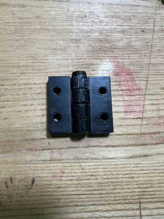
Align QTY (2) RP5 Door Hinge with each other by placing the circular ends in between each other. Each hinge should be flipped relative to the other hinge. Ensure it is in the following orientation:
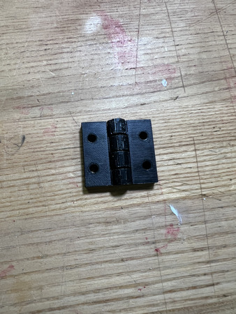
Insert QTY (1) Hinge Pin from the top, ensuring that it goes all the way through. Both Hinges are the same, so either orientation will work.
Insert QTY (1) M3x4x5 Heat Insert into QTY (1) RP5 Housing in the designated location using a soldering iron. Ensure that the top of the heat set inserts are flush with the surfaces.
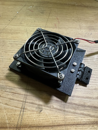
Attach the cool fan grill to the QTY (1) Brushless Cooling Fan using QTY (4) M3x10 Button Head Screw and QTY (4) M3 Hex Nut from the side WITHOUT the logo and wires. The screws should be going from the grill into the fan.
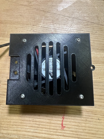
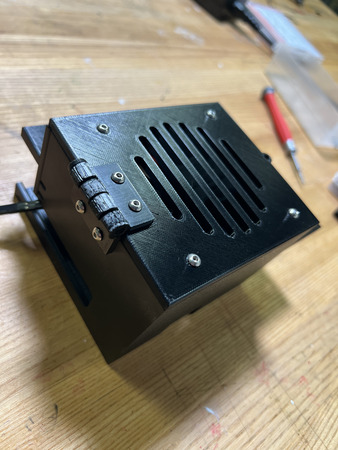
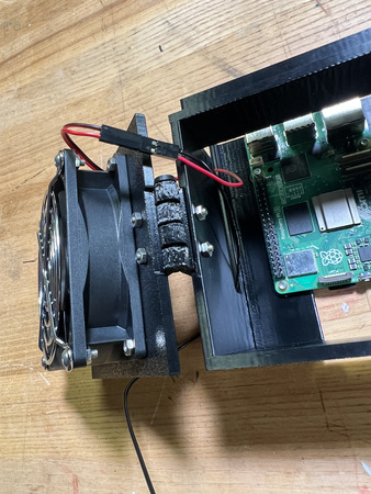
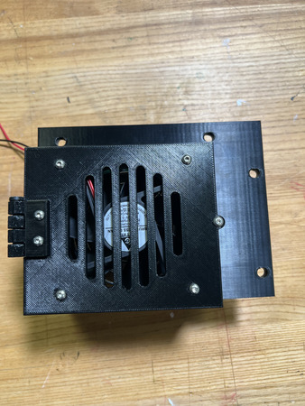
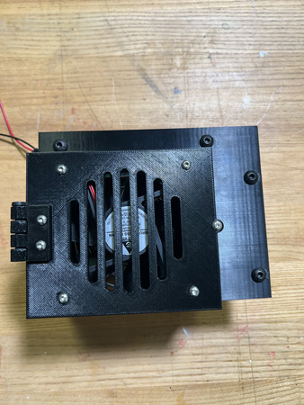
Attach the QTY (1) Brushless Cooling Fan to the back of the QTY (1) RP5 Housing Door (the side without the hinge indent) using QTY (4) M3x10 Button Head Screws and QTY (4) M3 Hex Nut. The fan should be orientated so that the wire is coming from the top left (while looking from the 3D printed door with the hinge indent on the left). The non-grill side of the fan should be interfacing with the door. The screws should be coming from the door to the fan (see image below).
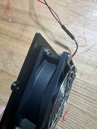
Attach one of the Hinges from the assembly in Step 2 to the hinge indent area on the RP5 Housing Door (opposite side of fan) using QTY (2) M3x10 Button Head Screw and QTY (2) M3 Hex Nut. The bottom of the hinge that touches the door should be the extruded side – not the flat side (see image below).
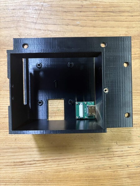
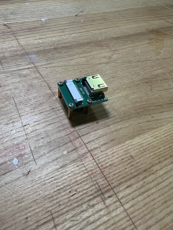
Attach QTY (4) M2x10 Standoff to QTY (1) CSI to HDMI Adapter in the corners and screw them in with QTY (4) M2x6 Button Head Screw.
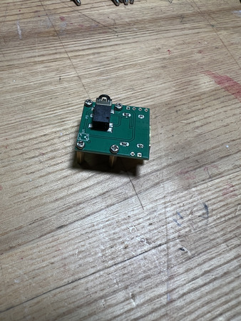
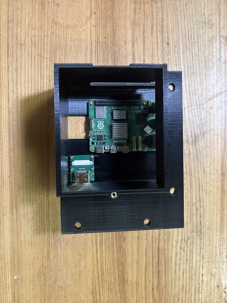
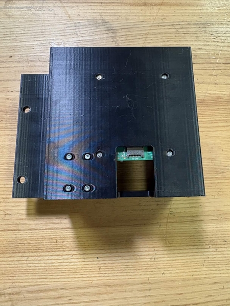
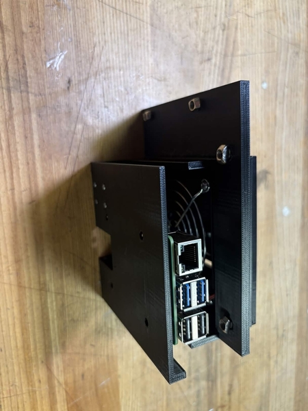
Attach the assembly from Step 7 in the section ‘2’ using QTY (4) M2x6 Button Head Screw from the opposite end of the 3D print, ensuring the port comes out on the right while looking from the door (see image below).
Attach QTY (1) Raspberry Pi 5 onto the RP5 in section ‘1’ using QTY (4) M2x6 Button Head Screw and QTY (4) M2x4x3.2mm Heat Set Insert. The ports on the Raspberry Pi should be on the top. Note: the M2 heat sets are not pictured as they were added later to replace the hex nuts.

Take the assembly from Step 6 and attach the other Hinge to the RP5 Housing at the RP5 Housing hinge indent using QTY (2) M3x10 Button Head Screw and QTY (2) M3 Hex Nut with the screws going from the Hinge to the Housing.
Close the door and lock it by screwing in QTY (1) M3x8 Button Head Screw in the designated location (see image below).
Insert QTY (4) M5x10 Button Head Screw from the top on each of the side mounting points as shown below. Loosely install QTY (4) M5 Hammer TNut on the opposite end of each fastener.
The Raspberry Pi Housing is now complete.
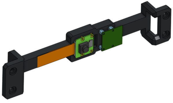
Camera Mount
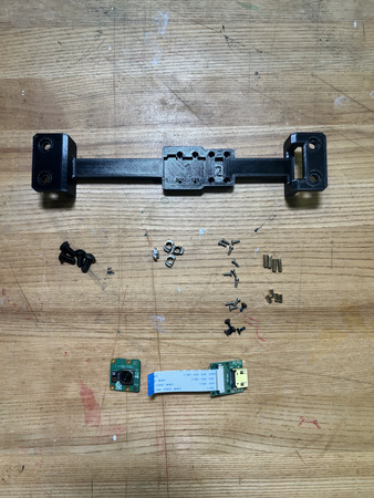
Required Materials:
(QTY 1) Camera Mount
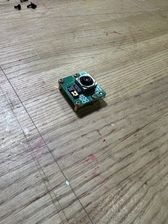
(QTY 1) Raspberry Pi Camera
(QTY 1) CSI to HDMI Adapter
(QTY 4) M5x10 Button Head Screw
(QTY 4) M5 Hammer TNut
(QTY 16) M2x6 Button Head Screw
(QTY 8) M2x10 Standoff
Required Tools:
Small Phillips Driver (+1.5)
Step-by-Step Instructions
NOTE 1: Unless otherwise mentioned, all fasteners will be “hand tight”.
NOTE 2: The flat side of the camera mount is the “back” (without the counterbores).
NOTE 3: The Wiring Section will install the ribbon cable that connects the camera to the adapter.
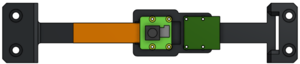
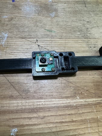
Install QTY (4) M2x10 Standoff to the bottom of the QTY (1) Raspberry Pi Camera using QTY (4) M2x6 Button Head Screw. The screw should go from the camera to the standoff.
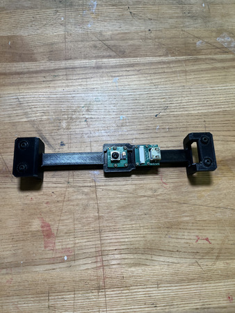
Install the assembly from Step 1 into the ‘1’ section using QTY (4) M2x6 Button Head Screw from the opposite end (with respect to the front–see image below). Ensure the camera ribbon cable goes to the left of the ‘1’.
Install QTY (4) M2x10 Standoff to the bottom of QTY (1) CSI to HDMI Adapter using QTY (4) M2x6 Button Head Screw. The screw should go from the adapter to the standoff.
Install the assembly from Step 3 into the ‘2’ section using QTY (4) M2x6 Button Head Screw from the opposite end (with respect to the front–see image below). Ensure the hdmi port faces the right of the ‘2’.
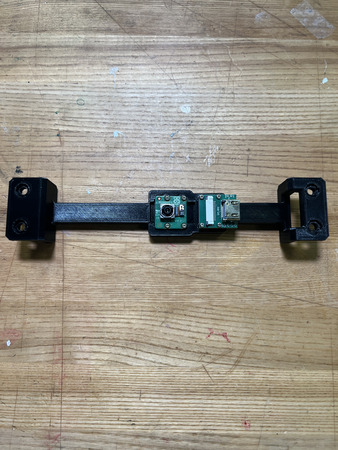
Insert QTY (4) M5x10 Button Head Screw from the top on each of the side mounting points as shown below. Loosely install QTY (4) M5 Hammer TNut on the opposite end of each fastener.
The Camera Mount subassembly is now complete.
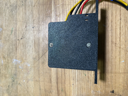
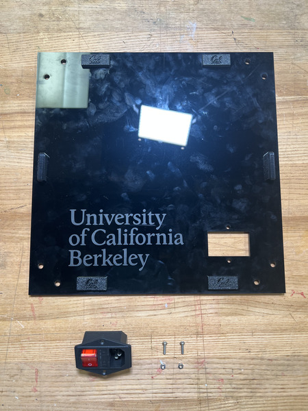
Switch
Required Materials:
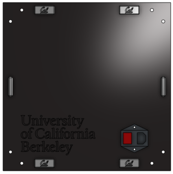
(QTY 1) Side Projector Panel subassembly
(QTY 1) Switch
(QTY 2) M3x10 Button Head Screw
(QTY 2) M3 Hex Nut
Required Tools:
M2 Hex/Allen Key
Step-by-Step Instructions
NOTE: Unless otherwise mentioned, all fasteners will be “hand tight”. The Side Projector Panel subassembly needs to be completed prior to this.
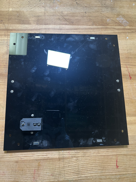
Place the QTY (1) Switch from the front of the QTY (1) Side Projector Panel subassembly in the position below. Ensure the switch is on the left and plug is on the right. Install using QTY (2) M3x10 Button Head Screw and QTY (2) M3 Hex Nut from the opposite side.
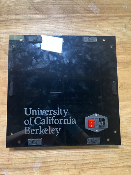
The Switch subassembly is complete.